CMM(Coordinate Measuring Machine) is an advanced measurement machine that works to measure complex and large components. CMM is a device for measuring the physical characteristics of an object. The machine is controlled by a computer or an operator. Learn more
CMM consists of 3-axis namely X-axis, Y-axis, Z-axis. Measurement is done by the prob attached to a third moving axis. This prob could be mechanical, optical, laser or white light.
So, the machine who takes reading in 6 DOF(Degree of freedom) known as CMM.
Components of CMM
The 3 main component of CMM are-
Machine itself (includes its 3-axis)
Probing System
Controllers & Softwares
Working Principle of CMM
CMM record X, Y, Z coordinates of the object and generate point which analysis by regression algorithm. This points are collected by Prob via direct computer control.
Main Parts of CMM
Air Bearing
Scales & Encoders
Prob system
Servo motors
Joystick
Machine control system
Software
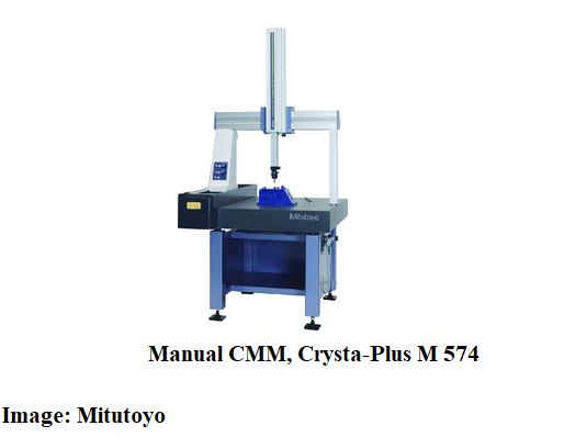
This is Mitutoyo’s manual floating bridge type CMM coordinate measuring machines designed to achieve very high accuracy in a wide range of applications.The model type is CRYSTA-PLUS M is the intelligent alternative to the complex, cost-intensive measuring equipment with conventional multi-point measuring devices.
Rack and Pinion are used for converting rotary motion to linear motion.
By OSHA Directorate of Technical Support and Emergency Management – Point of Contact Between a Rack and Pinion. The original uploader was Brian0918 at English Wikipedia., Public Domain, https://commons.wikimedia.org/w/index.php?curid=186765
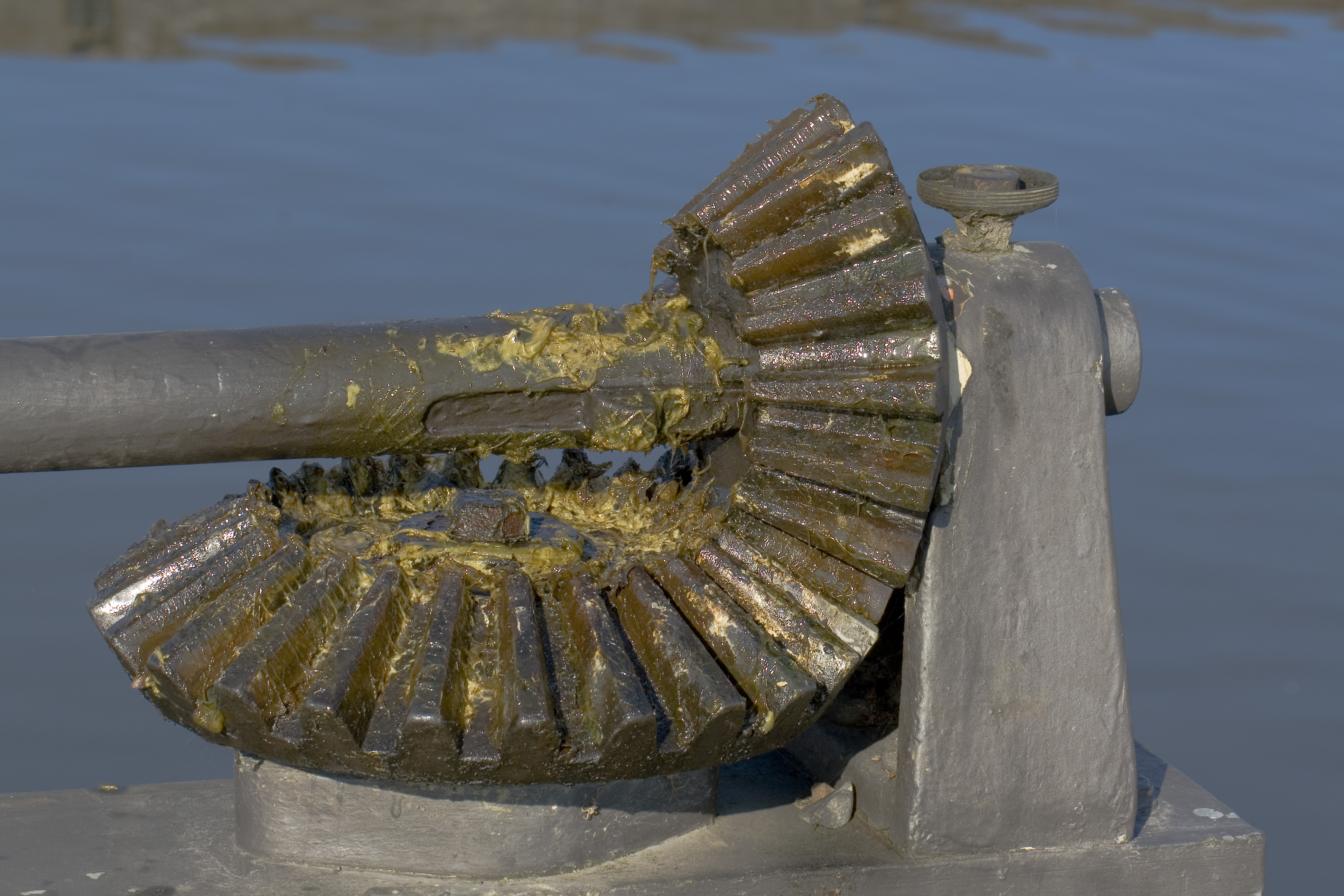
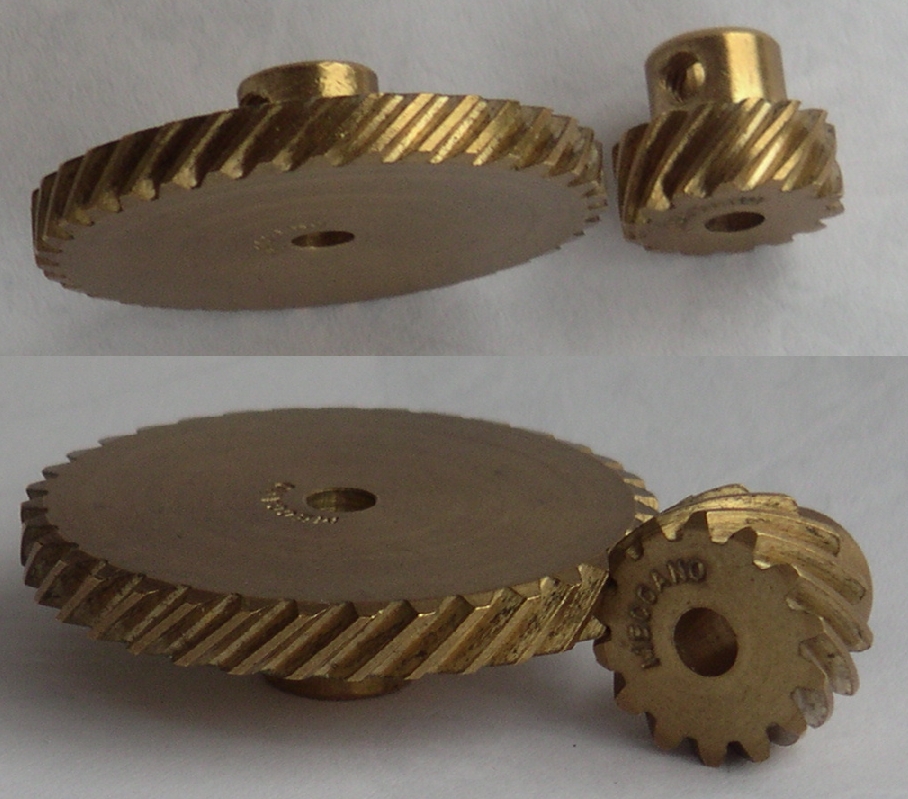
Spur Gears
This type of gear is widely used today. A spur gear, transmit a positive motion between two shafts lying parallel to each other.
Every gear rotates about its axis. So, all parameter have to be inspected about the axis of rotation.
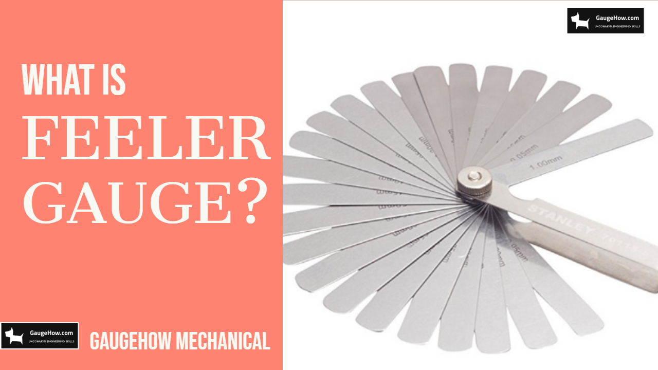
A Feeler gauge is used to measure the clearance between two parallel flat faces for example piston and cylinder. As the name suggests, feeler gauge called as to measure neither tide nor freely.
Watch the video of feeler gauge
Subscribe
Feeler gauges are used for measurement of clearances.
It is a tool that measures air or narrow gap widths between two surfaces in engines and machinery.
Size of Feeler gauge
Feeler gauge available in no. of the blade like 10,13,20 and 28. With a step of 0.05 and 0.10 mm.
The thickness of the blades are in fractions of mm and inches, usually ranging from 0.03 mm to 1mm.
Parts of Feeler gauge
The feeler gauge has two major parts, a body or block which acts like a protective case or shealth and a large number of blades of different thickness.
The body is the base that holds the blades together. Feeler gauges
are made entirely of steel so that they are corrosion free and the
blades do not rust easily.
In machinery and engine service, it is important to predict accurate measurement of gaps for smooth performance and to avoid any faulty operations.
It is extensively and mostly used for measuring the gap between an engine cylinder and piston.
When there is extra gap even after a blade is inserted then the blades of the feeler gauge can be used in various combinations as per the requirement, that is different blades having different thickness can be stacked together and used.
How to use Feeler gauge?
The working of feeler gauge is easy. The blades are kept on the
vacant gap that needs to be measured, initially one blade of standard
thickness is kept, then if there are extra gaps other blades are
adjusted and joined together and used.
Ensure that the blades can be easily pushed to and fro and are not tight nor free to move.
In order to have a problem-free measurement, the blades should be free of dirt and grease.
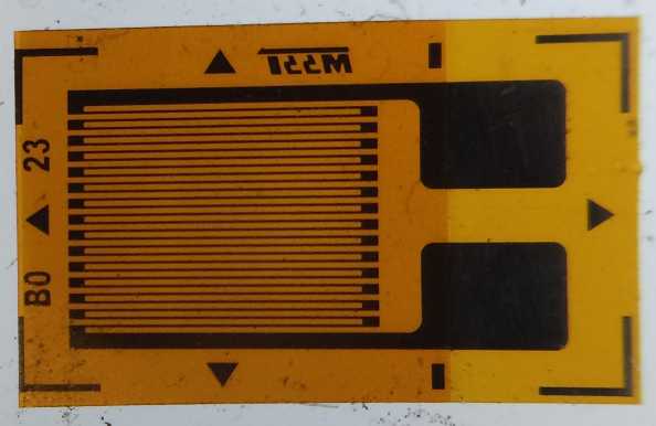
We all know about stress and stain and and its relation. But have you ever know about the measurement of Strain. please comment your valuable response.
The strain gauge is fundamental of many type of sensors like pressure sensors, load cells, torque sensors etc.
The most common form of strain gauge is the electrical resistance strain gauge.
The gauges are formed by either a length of wire arranged in an axial grid pattern or by etching a thin metal foil into the desired shape.
Doesn’t matter if you are a Mechanical, Civil, or other branch student/Engineer, Because this course is skill specific, which is Important & Useful in every field.
The transducer, which may be electrical, mechanical, optical, magnetic, piezoelectric, etc., converts the sensed information into a more convenient form.
The detecting or sensing element of a measuring system first makes contact with the quantity to be measured, and the sensed information is immediately transduced into an analogous form.
Classification of Transducers
Analog and Digital Transducers
In the case of analogue transducers, the input quantity is converted into an analogue output, which is a continuous function of time.
Whoops! There was an error and we couldn't process your subscription. Please reload the page and try again.
Simple D’Arsonval Type to Measure Current or Voltage
It essentially consists of components like a permanent
magnet, coil, hairsprings, pointer, and scale. The coil assembly is mounted on a shaft, which in turn is hinged on a hair spring.
To concentrate the magnetic fields, initially, the iron core is placed inside the coil.
The curved pole pieces are then attached to the magnet to ascertain if the torque increases as the current increases.
This means that electromagnetic energy is used to move the meter.
Volt-Ohm Milliammetersor Multimeters
The typical volt–ohm milliammeter employs switching provisions for connecting multipliers, shunt resistors, and rectifier circuits.
The current flowing through the resistor can easily be determined by switching over to the ohm-meter function, wherein the leads can be connected to the unknown resistance that causes the meter movement.
The advantage is that direct measurement is possible since the current flow indication is calibrated in terms of resistance
The vacuum tube voltmeter, popularly known as VTVM, is basically used to measure voltage.
To control the grid of the tube, proper multiplier resistors are employed through which the AC or DC input is given to the meter.
The input resistance of a VTVM is usually very high, when compared to that of a simple meter, due to high grid circuit resistance. This minimizes the loading of the signal source.
Cathode Ray Oscilloscope
A CRO is a voltage-sensitive device that is used to view, measure, and analyse waveforms.
Its advantage is that a beam of electrons with low inertia strikes the fluorescent screen, generating an image that can rapidly change with varying voltage inputs to the system.
The cathode ray tube (CRT) is the basic functional unit of CRO. The electron gun assembly comprises a heater, a cathode, a control grid, and accelerating anodes. When a cathode is heated, electrons are generated.
The accelerating anodes, which are positively charged, provide the necessary striking velocity to the emitted electron stream.
The electron beam, after gaining necessary acceleration, passes through horizontal and vertical deflection plates, which provide the basic movements in the X and Y directions.
XY Plotters
The XY plotters generate Cartesian graphs, which are obtained by two DC inputs, in X and in the Y-axis. It consists of two self-balancing potentiometers, one to control the position of the paper and others to control the position of the pen.
In XY plotters, the output is generated by plotting one emf as a function of the other emf.
Further, the emf, which is the output signal of transducers, may be a value of displacement, force, pressure, strain, or any other parameter.
Room temperature, body weight, sunshine,chest width and so on..
Almost every company are concerned with Quality management in the process of Introducing their work
First, we try to understand what is Metrology!
What is Metrology?
Metrology word derived from the Greek words Metro(means Measurement) and Logy(means Science).
Metrology includes all aspects with reference to measurements, whatever their level of accuracy.
Terminologies
Some technical terms are difficult to understand, so the following terminology is quite helpful for further studies
Accuracy
Accuracy is the closeness between a test result and accepted value.
Bias
Bias is the difference between the expected value and the accepted reference value.
Calibration
Calibration is the set of operations that establish under specified conditions, the relationship between values of quantities indicated by a measuring instrument or values represented by a material measure and the corresponding values realized by standards.
Drift
Drift is slow to change of a metrological characteristic of measuring instrument.
Magnification
The output result from a measuring device to be magnified many times to make it more readable, called Magnification.
Precision
Precision is the closeness of agreement between independent test results obtained under stipulated conditions.
Resolution
The smallest change of the measured quantity which changes the indication of a measuring instrument is called Resolution.
Traceability
Traceability means a measured result can be related to references.
We also measure depth through Vernier caliper, but Vernier caliper does not deliver as much as accuracy and precision, because extension rod of Vernier caliper has no standard, it used only for comparison purpose.
Depth micrometer used to measure the depth of an object with precision and accuracy with least count of 0.01 mm. The measuring span is 25 mm just like in micrometer, that can change by changing upsetting rod.
How to Measure with Micrometer?
Measuring Concept of Depth Micrometer is same as External Micrometer. The main differences are direction and position. Reading scale is Vertical in-depth micrometer and Direction of reading is opposite (starting from the end scale).
Enhance your Engineering Knowledge by Subscribe us
Specification
Some normal characteristics of Depth Micrometer describe follows
Accuracy
The accuracy of Depth Gauge is 0.01 mm which is fair enough for linear measurement and also accurate than vernier caliper. You can choose Digital Depth Micrometer, in order to simplify observation only. Both types of Depth Micrometer delivers the same accuracy.
Standard
Depth Micrometer follows national or international measurement standard, while vernier caliper is not(in order to check depth through extension rod only).
Cost
The cost of Depth Micrometer is low than digital type. Cost may be
varied brands to brands, usually depend upon the quality of material
used. Some most famous Brands which are known for their quality promise
available in a market like Mitutoyo, baker etc.
The main use of depth micrometer is to check the depth of any objects. Basically used in industrial areas of manufacturing plants.