
PC-DMIS vs ZEISS Calypso Comparison 2025 - Field Guide
Learn More in This Video
Subscribe to GaugeHow for More
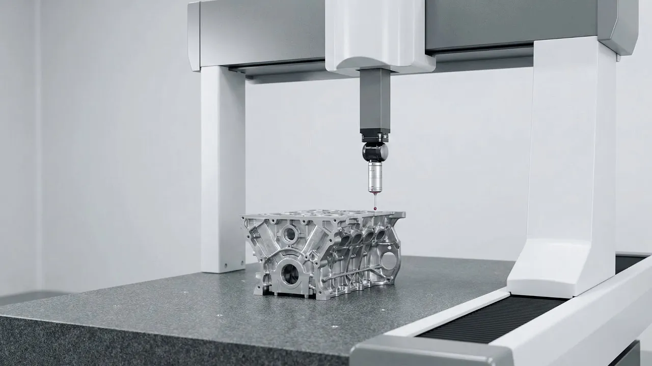
Imagine your production floor for a second.
You have mixed equipment. You have tight cycle times. You have a new metrology engineer starting on Monday.
Choosing PC-DMIS vs ZEISS Calypso isn't just about buying a software license. It is a critical operational choice.
It determines everything.
How do you automate?
How do you validate?
How do you govern inspection across every single production line?
This guide is not for casual readers. It is for the metrology leads. The senior programmers. The process owners who are tasked with a heavy burden: migrating, consolidating, or designing mixed-brand inspection cells.
We are not here to discuss history. Expect clear rules. Short checklists. Numeric validation steps.
You can paste these directly into your SOPs today.
Executive Summary (Quick Decision)
Choose PC-DMIS for Control.
You need deep scripting. You need to integrate mixed brands. You require complex retry loops and external I/O control.
PC-DMIS is built for this specific reality. It is the integration hub for heterogeneous cells.
Choose ZEISS Calypso for Speed.
You prefer visual GD&T. You need to onboard operators fast. You want tight integration with ZEISS controllers and probe heads.
Calypso excels here. It wins at plan-driven, visual validation workflows.
A Critical Warning on Converters.
Stop looking for a magic button.
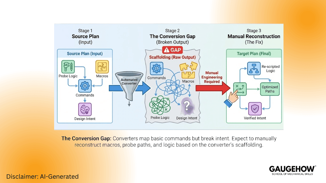
Do not treat converters as a drop-in migration tool.
Use converters only to scaffold your work. Expect to do the heavy lifting manually. You will need to reconstruct intent. You will need to fix the probe logic.
Comparison of PC-DMIS and ZEISS Calypso
Feature | PC-DMIS | ZEISS Calypso | Practical Winner |
Programming Model | Linear, explicit, scriptable | Visual, object-tree, plan-driven | PC-DMIS for automation |
GD&T & Reporting | Explicit construction & math | Visual GD&T and PMI import | Calypso for visual clarity |
Automation | Deep scripting, loops, external I/O | Template workflows, pattern programming | PC-DMIS for mixed cells |
Learning Curve | Steeper for programmers | Faster for operators | Calypso for shop-floor speed |
Hardware Fit | Broad I++ / DME ecosystems | Optimized for ZEISS hardware | Depends on cell vendor mix |
Why the Programming Model Matters
Visibility vs Control: Calypso exposes datums and features in a visual tree, which significantly reduces interpretation errors for operators and auditors.
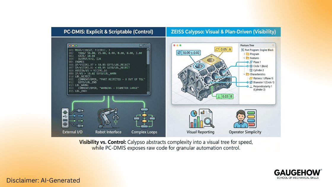
Traceability vs Flexibility: PC-DMIS exposes every motion and evaluation step. This provides traceable calculations (critical for aerospace/safety-critical parts) and enables robots, external triggers, and complex retry logic.
Conversion Reality: What Actually Breaks
Converters map commands, not intent. When performing a PC-DMIS vs ZEISS Calypso comparison 2025 migration, expect the following to require manual intervention:
Conditional logic and custom macros.
Probe approach vectors, retract rules, and stylus stacks.
Filtering, smoothing parameters, and datum construction steps.
Field Note: Treat converter output as scaffolding only. You must perform numeric parity tests. Community experience confirms conversions often require significant manual tuning to match uncertainty thresholds.
Migration Roadmap — Engineering Playbook
Phase 0 — Governance & Scope
Create a migration register (plan name, owner, risk tag, stylus file reference).
Define acceptance limits per feature (e.g., plus or minus 2 micrometers or percent tolerance). Tie this directly to product risk.
Phase 1 — Inventory & Risk Tagging
Export plan list, macros, and stylus files.
Tag Plans:
Green: Simple features.
Amber: Moderate macros/filters.
Red: Heavy macros + mixed sensors.
Phase 2 — Early Conversion & Numeric Parity
Select representative Green and Red plans.
Run 5 consecutive cycles on the source machine; export raw point clouds for each cycle.
Convert the plan; run 5 cycles on the target machine; export raw point clouds.
Compare raw points feature-by-feature (mean bias, standard deviation, positional bias). Accept only if bias and uncertainty meet your pre-defined thresholds.
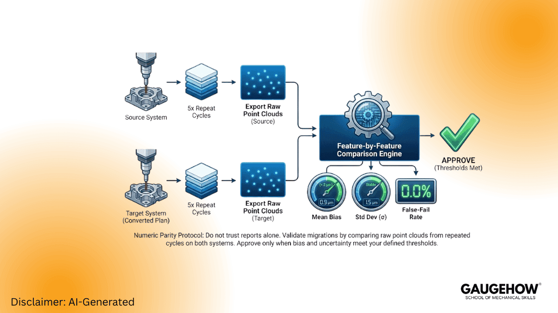
Quick Comparison Metrics to Capture (Per Feature):
Mean difference (micrometers )
Standard deviation (micrometers )
False-fail rate (%)
Cycle time (s)
Phase 3 — Bench Pilot then Floor Pilot
Bench Pilot: Controlled environment, single operator, supervised runs, log mismatches.
Floor Pilot: Production operator runs, blind checks against source system results for N=30 parts. Approve if KPI thresholds hold.
Phase 4 — Rollout & Maintenance
Lock plans by user role.
Archive raw point exports with version stamps.
Revalidate after any controller, firmware, or software update.
CMM Program Conversion Checklist
Use this checklist to validate your PC-DMIS vs ZEISS Calypso migration:
Export raw point clouds (Source System).
Confirm identical probe configuration (tips & lengths).
Export approach vectors & retract routines.
Record filter/smoothing parameters.
Translate macros into native scripting manually.
Align datum construction steps numerically.
Run five repeats on both sides and compare results.
Approve only after uncertainty thresholds pass.
Performance Engineering for Fast Cells
Group Features: Minimize probe changes and index moves to reduce non-value-added time.
Use Loops: PC-DMIS loop strategies reduce motion overhead significantly compared to linear programming.
Head Optimization: Minimize axis settling and avoid unnecessary probe-head flips during critical measurement sequences.
Validation KPIs (What to Measure)
Cycle time (s/part)
False-fail rate (%)
Operator ramp time (hours to proficiency)
Feature repeatability (sigma, micrometers )
Expanded uncertainty (k=2)
Critical Rule: If migration increases expanded uncertainty, stop the rollout, isolate datums and probe logic, and revalidate.
Field Examples
Aerospace Bracket (Anonymized)
Scenario: Calypso -> Converted Plan.
Initial Result: Cycle time increased +21% (510s -> 420s).
Optimization: After scripting optimizations and datum realignment, cycle time dropped to -18% vs source, and bias was reduced to <2 micrometers .
Mixed Cell Consolidation
Scenario: Migrated critical plans to PC-DMIS to act as a central hub.
Result: False-fail rate dropped from 6% to 1.5%, and expanded uncertainty improved on critical features due to better retry logic.
FAQs
1. Which tool is better for automation-heavy cells?
PC-DMIS — it offers superior scripting, external I/O handling, and mixed-brand support.
2. Can converters do the job alone?
No. Converters help scaffold the program, but rarely migrate "intent" perfectly. Always run raw-point parity tests.
3. Can both software platforms coexist?
Yes. Use each where it fits: Calypso for tight ZEISS cells and operator-driven visual plans; PC-DMIS for high-automation hubs.
Mechanical Engineering Courses That Industry Actually Uses
Learn Tools of Design & CAD, Analysis & Simulation, Automation & Robotics, and Industry 4.0 used in modern factories.
Join 40+ Mech Courses like GD&T, Siemens NX, SolidWorks, CATIA V5, AutoCAD, ANSYS (FEA & Fluent), ABAQUS, Creo, Fusion 360, CNC Programming, Digital Twins, Python for Mechanical, and Industry 4.0.
Our Courses
Complete Course Library
Access to 40+ courses covering various fields like Design, Simulation, Quality, Manufacturing, Robotics, and more.


