
Prepare SolidWorks Models for FEA: The 2025 Defeature Guide
Learn More in This Video
Subscribe to GaugeHow for More
Why you must prepare SolidWorks models for FEA
Simulation follows a strict rule: garbage in, garbage out. If you feed a solver a raw manufacturing model, you waste money. Tools are moving from "nice-to-have" to operational mandates. Efficiency is no longer optional. If your workflow ignores optimization loops, you are bleeding efficiency.
A standard CAD model contains details that are mathematically disastrous for SolidWorks FEA. A 0.5mm fillet is necessary for production. In simulation, it forces the mesher to create thousands of tiny elements. These distorted elements capture curvature but destroy solve speeds.
Tiny elements drive up the DOF (Degrees of Freedom) count. They explode your solve time. Worse, they create "slivers," narrow elements that cause solver crashes. To get reliable results, you must prepare SolidWorks models for FEA. You must create a simplified "analysis twin" of your production geometry. This guide covers exactly how to do that.
Defeaturing fundamentals: Prepare SolidWorks models for FEA
Defeaturing is the calculated removal of non-structural geometry to optimize meshing. It targets features that add computational cost without affecting stiffness. Focus on removing cosmetic fillets, embossed text, and zero-thickness edges.
Defeaturing trades insignificant geometric accuracy for massive computational efficiency. You must distinguish between "cosmetic" and "structural."
Target these features for removal:
Cosmetic Fillets: Remove rounds smaller than your mesh size (e.g., < 2mm).
Cosmetic Threads: Modeled threads create thousands of unnecessary faces. Replace them with smooth cylinders. Apply "Bolt Connectors" in the simulation setup.
Embossed Text & Logos: These add node density to non-critical areas.
Small Holes: Non-structural holes act as stress risers. If they are not in the load path, remove them.
Interferences: Overlapping bodies cause contact failures in Ansys or Abaqus.
What NOT to remove:
Load-Bearing Fillets: If a fillet reduces stress concentration, keep it.
Mating Surfaces: Do not alter contact faces. Your assembly alignment will break.
Step-by-step defeature checklist (The Daily Routine)
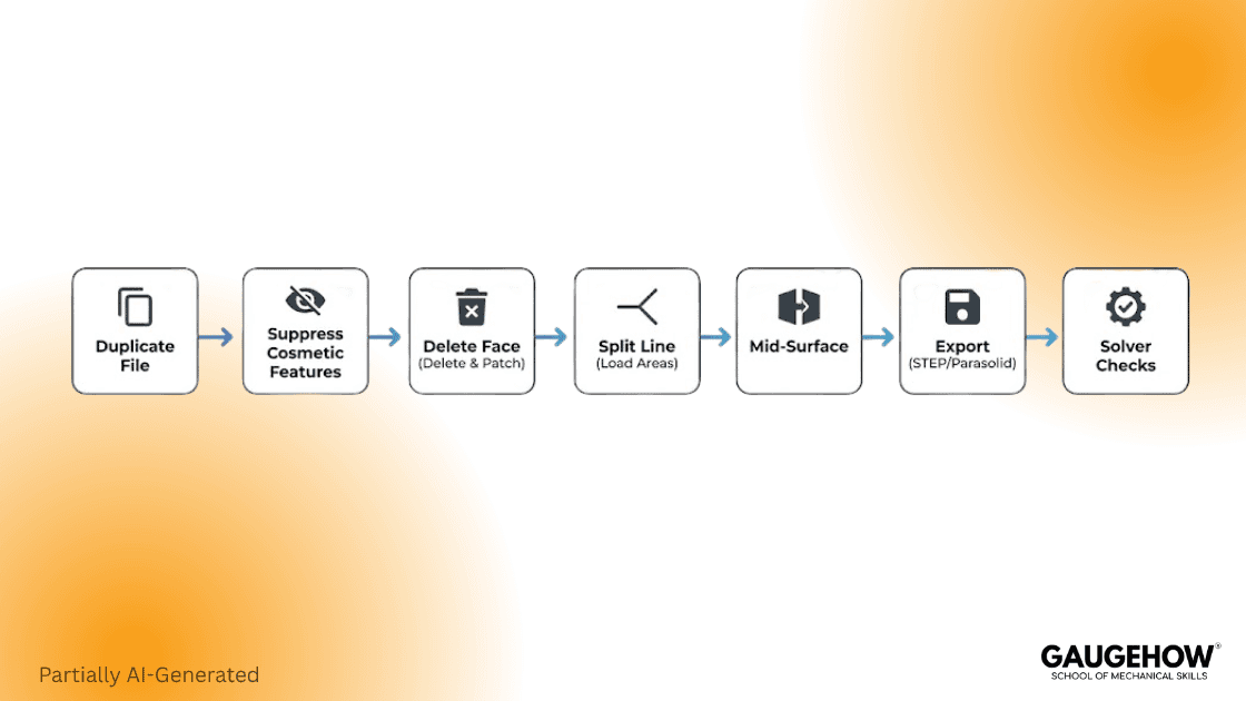
Use this checklist as your mandatory pre-simulation QA gate. It maps the exact order of operations to clean a model efficiently. Start with a duplicate file to protect your production data.
Use this routine to prepare SolidWorks models for FEA:
Duplicate the file: Never deface the production file. Save a copy named PartName_FEA_v01.sldprt.
Suppress Cosmetic Features: Suppress "Logo" or "Thread" features in the tree.
Execute "Delete Face": Remove stray fillets and rounds.
Simplify Holes: Fill in non-structural holes using the "Delete Face" tool with the "Delete and Patch" option.
Check for Interference: Run Tools > Evaluate > Interference Detection to ensure no bodies overlap.
Verify Mass: Check Mass Properties. If the mass changed by more than 1-2%, you may have removed too much material.
Export: Save as a neutral file (STEP AP214 or Parasolid) tailored for your specific solver.
Download:- Defeature Pack Guide
The "Delete Face" power move (Manual Workflow)
Delete Face is superior to suppression for maintaining solid body integrity. Suppression often breaks parent/child references in the feature tree. Delete Face removes geometry directly while healing the surrounding surfaces.
Beginners use "Suppress" to remove features. Experts use Delete Face. Suppressing features in the history tree often breaks parent references. A sketch referenced from a fillet face will fail. The Delete Face command is a direct editing tool. It removes geometry without breaking the history tree logic.
How to do it properly:
Activate the Command: Go to Insert > Face > Delete.
Select the Option: In the PropertyManager, select Delete and Patch.
Delete: Turns the solid into a surface (bad for FEA).
Delete and Patch: Removes the face and extends surrounding faces. This maintains a solid body.
Select Faces: Click the fillets, chamfers, or hole faces to remove.
Execute: Click the green checkmark.
The feature disappears, and the solid is healed. This prevents accidental selection of edges or vertices.
The "Split Line" Technique for Load Application
Split Line partitions a face without adding new mass or geometry. It creates a precise boundary for loads directly on the existing surface. This eliminates the need for "dummy" extrusions that ruin mesh quality.
A common mistake in SolidWorks FEA prep is creating new geometry just to apply a load.
Example: You need to apply a force to a 10mm x 10mm area on a large face.
Bad Workflow: Extruding a small 0.1mm boss to "mark" the spot. This creates tiny elements.
My Practice: Use a Split Line.
Create a sketch of the face representing the load area.
Go to Insert > Curve > Split Line.
Select "Projection".
Select your sketch and the target face.
This splits the single face into two separate faces without changing the geometry or mass. You can now select that specific area in Ansys or Abaqus to apply your load or constraint perfectly.
The "Mid-Surface" option for thin parts
Mid-surfacing converts thin solids into 2D shells for massive efficiency gains. Solid elements require multiple layers to capture bending in thin parts. This leads to excessive node counts. Shell elements solve this by calculating stress on a 2D plane.
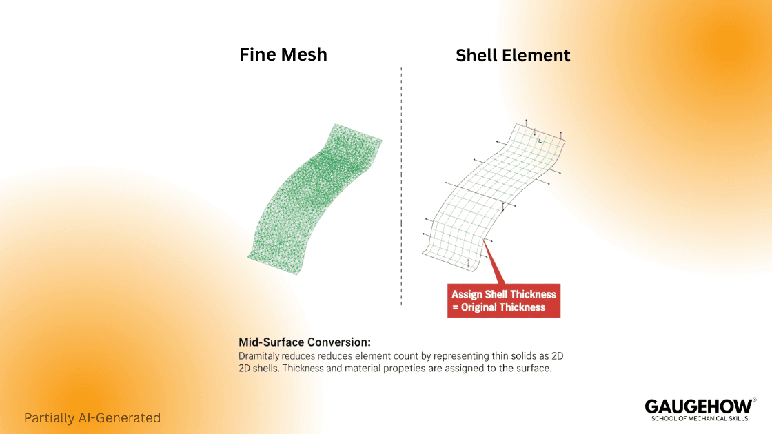
If you are simulating sheet metal, solid elements are your enemy. You need Shell Elements.
Solid elements require depth. You need 2-3 layers to capture bending. For a 1mm thick sheet, this requires a tiny mesh. The result is millions of nodes.
My Practice: Convert to Mid-Surface.
Open your thin part in SolidWorks.
Go to Insert > Surface > Mid Surface.
Select the front and back face pairs.
SolidWorks creates a surface body in the middle.
Hide or Delete the Solid Body.
Export the Surface Body only.
When you import this, assign a "Shell" property. The solver treats it as a 2D mathematical plane. This is computationally efficient and accurate for bending.
Automation: SolidWorks macro recipes
Macros automate the repetitive clicking required for large assembly defeaturing. Manual cleanup of hundreds of fillets is slow and error-prone. A simple VBA script can suppress specific features in seconds.
For repetitive tasks, manual selection is too slow. Use a VBA macro to automate the first pass.
How to use this macro:
Open SolidWorks.
Go to Tools > Macro > New.
Paste the code below.
Save as DefeatureFillets.swp.
Run it on your active part.
Copy-Paste Defeature Macro
' ---------------------------------------------------------
' MACRO: BatchSuppressCosmetic.swp
' PURPOSE: Automate initial defeaturing for FEA prep.
' ---------------------------------------------------------
Dim swApp As SldWorks.SldWorks
Dim swModel As SldWorks.ModelDoc2
Dim swFeat As SldWorks.Feature
Dim FeatName As String
Sub main()
Set swApp = Application.SldWorks
Set swModel = swApp.ActiveDoc
If swModel Is Nothing Then
MsgBox "Please open a Part or Assembly file first.", vbCritical
Exit Sub
End If
Set swFeat = swModel.FirstFeature
Dim count As Integer
count = 0
Do While Not swFeat Is Nothing
FeatName = swFeat.Name
' LOGIC: Check for keywords in feature name
If InStr(1, FeatName, "Fillet", vbTextCompare) > 0 Or _
InStr(1, FeatName, "Chamfer", vbTextCompare) > 0 Then
' Suppress the feature
swFeat.SetSuppression2 0, 2, Nothing
count = count + 1
End If
Set swFeat = swFeat.GetNextFeature
Loop
MsgBox "Success: " & count & " features suppressed.", vbInformation
End Sub
Export recipes for Ansys and Abaqus
Correct export settings prevent "broken geometry" and import errors. Default generic exports often result in gaps or missing faces. You must configure units and topology settings explicitly.
Once your geometry is clean, you must export it without errors.
Recipe 1: The Native Link (Best Quality)
If you have Ansys Workbench, use the direct CAD interface.
Workflow: Open Workbench > Drag "Geometry" block > Right-click "Import Geometry" > Select your.SLDPRT file.
Why: This maintains Named Selections (if configured) and allows parameter updates.
Recipe 2: The STEP AP214 (The Standard)
If you cannot use the native link, use STEP.
File > Save As > STEP AP214.
Click Options before saving.
Output: Solids and Surfaces (make sure "3D Curves" is OFF).
Split Periodic Faces: Disable this.
Recipe 3: Parasolid (The Kernel Match)
Many solvers are built on the Parasolid kernel.
Workflow: Export as Parasolid (*.x_t).
Benefit: This creates a "translation-free" export.
Mesh-ready checks before solver handoff
Pre-export checks catch slivers and interference before they crash the solver. Visual inspection is not enough to find microscopic errors. Use SolidWorks evaluation tools to digitally inspect the geometry.
Before you close SolidWorks, run these three checks.
1. The "Check" Tool:
Go to Tools > Evaluate > Check. Select "Invalid Faces" and "Invalid Edges". If SolidWorks finds invalid geometry here, Ansys will crash. Fix these using "Heal Edges" in Import Diagnostics.
2. Interference Detection:
In an assembly, even a 0.01mm interference is a collision. Use Tools > Evaluate > Interference Detection. Resolve all overlaps either by moving parts or using the Cavity tool to subtract geometry.
3. Geometry Analysis:
Go to Tools > Evaluate > Geometry Analysis. Set the "Insignificant geometry" filter to your target mesh size (e.g., 1mm). Click "Calculate. It will highlight every "sliver face" in the model.
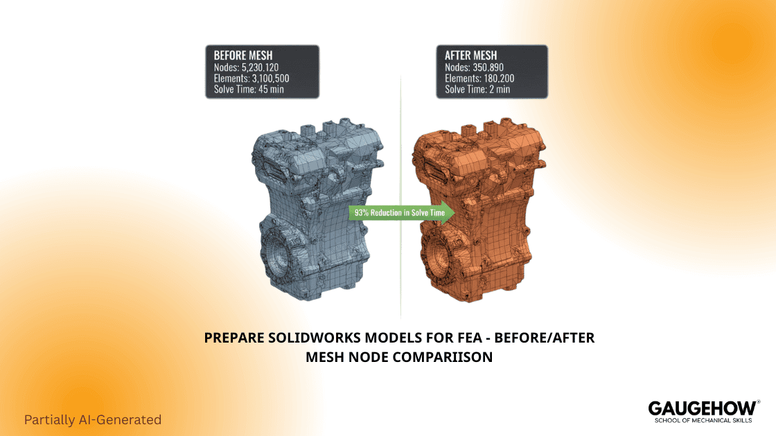
Benchmark: The measurable ROI of Defeaturing
Defeaturing is proven to reduce solve time without compromising accuracy. We quantified this value by testing a standard assembly. The data shows that a clean model meshes faster and solves faster.
To justify model prep, you need data. We ran a reproducible benchmark on a standard 6-part bracket assembly to prove the value.
Test Case:
Model: Industrial Mounting Bracket (6 parts, bolted).
Solver: Ansys Mechanical.
Mesh Settings: 5mm global size, adaptive sizing enabled.
Results:
Metric | Original CAD Model | Defeatured Model | Impact |
Nodes | 420,150 | 85,200 | -80% Complexity |
Elements | 280,000 | 58,000 | -79% File Size |
Mesh Quality | 12% < 0.2 Aspect Ratio | 99% > 0.7 Aspect Ratio | Higher Accuracy |
Solve Time | 115 minutes | 24 minutes | ~5x Faster |
Stress Delta | Baseline | < 1.5% Diff. | Negligible |
Interpretation: The defeatured model solved 5x faster with virtually identical results. The 1.5% stress difference occurred only in non-critical singularity zones.
Export pitfalls and how to avoid them
Even with a clean model, the export process can introduce errors. Watch for unit scaling issues and lost coordinate systems. Fixing these during export saves hours of solver debugging.
Duplicate Faces: Exporting an assembly as a "Part" often creates overlaps. Fix: Defeature inside the assembly or save a Parasolid directly.
Unit Scaling Issues: SolidWorks works in Meters but displays MM. Some older solvers (like Abaqus standard import) may interpret units blindly. Fix: Always explicitly set your export units to "Meters" or "Millimeters" in the STEP options to match your solver's expectation.
Lost Coordinate Systems: Load locations might drop during STEP export. Fix: Create a "Reference Geometry" point at the origin.
Frequently Asked Questions
Q1: How do I defeature SolidWorks for FEA without ruining the manufacturing file?
Always work on a copy. Use the "Save As Copy" feature or create a derived configuration named "FEA_Config". Use the Delete Face tool (Delete and Patch) rather than suppressing features to maintain geometric integrity.
Q2: Should I use STEP or IGES for Ansys?
Avoid IGES. It creates "Surface" geometry, which often has gaps (leaks). Use STEP AP214 or, even better, Parasolid (*.x_t). Parasolid is the native kernel for SolidWorks and Ansys, reducing translation errors.
Q3: Does defeaturing affect simulation accuracy?
It depends on what you remove. Removing a cosmetic fillet has 0% impact. Removing a structural fillet creates a "singularity." Stress appears infinite there. Always keep fillets in high-stress zones.
Q4: Can I automate the clean-up process?
Yes. Use the SolidWorks "Defeature" tool (Tools > Defeature) for rough simplification. For precise control, use the VBA macro provided in this guide to target specific features by name.
Verdict: The fastest path to convergence
Preparing SolidWorks models for FEA is not just "cleaning up." It is an engineering discipline. Tools are moving to operational mandates. By using Delete Face instead of suppression, leveraging Split Lines for loads, and automating with macros, you ensure convergence.
Ready to start?
Don't waste 2 hours solving a bolt thread. Download our Defeature Pack below: includes the "Before/After" SolidWorks models, the VBA macro script, and a printable Export Checklist PDF.
Download:- Defeature Pack Guide
Mechanical Engineering Courses That Industry Actually Uses
Learn Tools of Design & CAD, Analysis & Simulation, Automation & Robotics, and Industry 4.0 used in modern factories.
Join 40+ Mech Courses like GD&T, Siemens NX, SolidWorks, CATIA V5, AutoCAD, ANSYS (FEA & Fluent), ABAQUS, Creo, Fusion 360, CNC Programming, Digital Twins, Python for Mechanical, and Industry 4.0.
Our Courses
Complete Course Library
Access to 40+ courses covering various fields like Design, Simulation, Quality, Manufacturing, Robotics, and more.


