
Limit, Fit & Tolerance
Learn More in This Video
Subscribe to GaugeHow for More
A large number of parts with exactly the same dimensions cannot be produced commercially. In practice, the actual dimension of a component is always slightly larger or smaller than the desired dimension.
The desired dimension of a component is called the nominal dimension.
The permissible deviation of the actual dimension from the nominal dimension is known as tolerance.
The maximum and minimum permissible dimensions of a part are called its limits.
Manufacturing tolerance is essential to ensure interchangeability of parts, which in turn enables proper functioning and economical mass production.
Limit System
A limit system consists of a series of tolerances arranged for a specific range of sizes in order to obtain desired classes of fit between mating components.
There are two basic systems of limits:
1. Basic Hole System
In the basic hole system, the hole size is kept constant at the basic size, and the shaft size is varied to obtain the required fit.
This system is widely preferred because:
Standard tools such as drills, reamers, broaches, and plug gauges are not adjustable
Shafts can be easily machined to obtain different fits
2. Basic Shaft System
In the basic shaft system, the shaft size is kept constant at the basic size, and the hole size is varied to obtain the required fit.
This system is used when:
Shafts are produced by standard processes
It is difficult or uneconomical to vary shaft dimensions
Fit System
The degree of tightness or looseness between mating parts is known as the fit.
The type of fit depends on the relative sizes and tolerances of the mating components.
Fits are broadly classified into three categories:
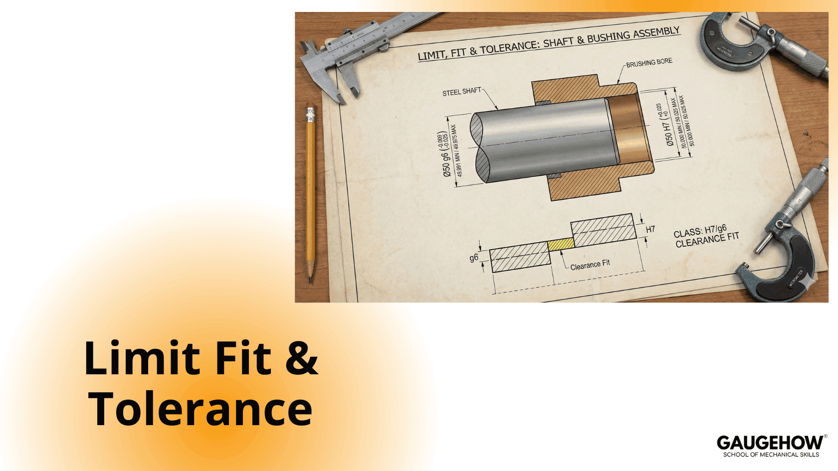
1. Clearance Fit
In a clearance fit, there is always a positive clearance between the shaft and the hole.
The maximum shaft size is smaller than the minimum hole size
Suitable for free movement or rotation
Examples: running fit, sliding fit
2. Interference Fit
In an interference fit, the shaft is always larger than the hole.
The minimum shaft size is greater than the maximum hole size
Assembly requires force or heating
3. Transition Fit
A transition fit may result in either clearance or interference, depending on the actual sizes.
This is achieved when:
The upper limit of the shaft is greater than the lower limit of the hole
The lower limit of the shaft is smaller than the upper limit of the hole
Tolerance System
Tolerances on dimensions can be specified in three ways:
1. Unilateral Tolerance System
In this system, tolerance is provided only in one direction from the basic size.
Example:
35.00 +0.20 / +0.50 mm
2. Bilateral Tolerance System
In this system, tolerance is provided in both directions from the basic size.
Example:
35.00 +0.20 / −0.50 mm
3. Limit Dimension System
In this system, the size of the part is specified directly by its maximum and minimum limits, without mentioning tolerance.
Example:
35.2 mm to 35.5 mm
Mechanical Engineering Courses That Industry Actually Uses
Learn Tools of Design & CAD, Analysis & Simulation, Automation & Robotics, and Industry 4.0 used in modern factories.
Join 40+ Mech Courses like GD&T, Siemens NX, SolidWorks, CATIA V5, AutoCAD, ANSYS (FEA & Fluent), ABAQUS, Creo, Fusion 360, CNC Programming, Digital Twins, Python for Mechanical, and Industry 4.0.
Our Courses
Complete Course Library
Access to 40+ courses covering various fields like Design, Simulation, Quality, Manufacturing, Robotics, and more.


