Composite Material: Definition, Types, Properties


Deepak S Choudhary
Composite materials combine two or more distinct constituents that stay separate in the final structure, yet work together to deliver targeted performance. This guide covers definition, common examples, major types, how composites are made, and the properties that drive real decisions. It also adds a practical FEA translation later.
Most people land on “composite material” because they want a clean overview. That means a definition that holds up, common examples they recognize, how the material is made, and a balanced pros and cons view. Engineers need one extra layer because composites are directional. A laminate can be stiff along fibers and soft across them, so the same part can look safe in one direction and fail in another.
To avoid confusion, one quick disambiguation helps. “Composite decking” is a consumer product category with buying intent. This page is about engineering composites like reinforced concrete, plywood, fiberglass, carbon laminates, and sandwich panels.
Definition And Quick Examples
A composite material is built from distinct constituents that remain separate in the finished structure. That “remain separate” rule is the key separator between mixtures and solid solutions. In most engineered composites, a matrix binds and transfers load, while a reinforcement carries most of the load.
Common examples that match the head term intent:
Reinforced concrete: steel carries tension, cementitious matrix carries compression.
Plywood: layered veneers create directional stiffness and stability.
Fiberglass (GFRP): glass fibers plus polymer matrix.
Carbon fiber laminate (CFRP): carbon fibers plus resin, built in plies.
Sandwich panels: stiff faces bonded to a light core for bending efficiency.
A term you will see often is laminate. A laminate is a multi-layer composite where ply orientation and stacking order change stiffness, strength, and failure behavior.
Composite Vs Plastic Vs Alloy Vs Mixture
Material Class | What It Is | Key Practical Difference |
Composite | Distinct constituents remain separate | Properties depend on architecture and direction |
Plastic (polymer) | Mostly one continuous phase | More isotropic behavior, simpler allowables |
Alloy | Mixed metals in a solid solution or phases | Strong process-property link, but not ply directional |
Mixture | Blended materials without an engineered structure | Not designed for structural load sharing like composites |
How We Think Differently At GaugeHow
Good composite decisions come from simple gates. You lock what the composite is, you lock how it is built, and you lock what question you are answering. That prevents clean plots and nice words from replacing proof.
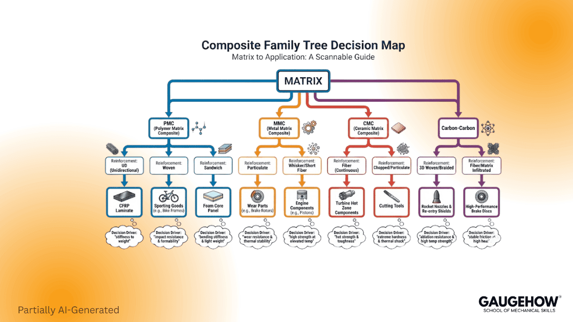
Types Of Composite Materials
Type | What It Means | Common Examples |
Fiber Reinforced | Fibers carry most load | GFRP, CFRP |
Particulate Composites | Particles reinforce a matrix | Reinforced concrete, filled polymers |
Laminates | Layered plies with different directions | Plywood, carbon laminates |
Sandwich Structures | Stiff faces plus a light core | Foam or honeycomb panels |
Types By Matrix Family
Polymer Matrix Composites (PMCs)
These are the most common structural composites in day-to-day products. They are practical to manufacture and have deep data coverage. You will see them in sporting goods, automotive parts, wind blades, marine structures, and aerospace interiors.
Metal Matrix Composites (MMCs)
MMCs use a metal matrix with ceramic or carbon reinforcement. They are chosen for higher temperature capability and wear resistance, but processing is harder, andthe density is higher than that of polymers.
Ceramic Matrix Composites (CMCs)
CMCs are built for high-temperature applications where polymers fail. You see them in demanding thermal environments where oxidation, creep, and hot strength dominate.
Carbon-Carbon (C/C)
Carbon fibers in a carbon matrix are a high-temperature niche, often tied to extreme thermal cycling and friction environments.
A quick note on “nanocomposites.” They usually sit inside PMCs, where nanoscale fillers are used to shift stiffness, electrical behavior, barrier performance, or wear.
Experience Note:-
PMCs: Best data coverage and easiest processing, so they win most structures.
MMCs: Chosen for wear and temperature, but mass and cost rise fast.
CMCs: Selected when hot strength matters, with higher process complexity.
Carbon carbon: Extreme thermal niche, strong at heat, weak to oxidation risk.
Applications Of Composite Materials
Industry | Why Composites Are Used | Common Composite Examples |
Aerospace | Mass reduction, stiffness tailoring, fatigue performance | CFRP laminates, sandwich panels, CMC hot-zone parts |
Automotive | Mass reduction, crash tuning, corrosion resistance | GFRP, CFRP, PMC, SMC, hybrid laminates |
Wind Energy | High specific stiffness for long blades | GFRP, carbon spar caps, sandwich skins |
Marine | Corrosion resistance, stiffness, and mass efficiency | GFRP hulls, CFRP masts, foam-core sandwich |
Construction | Strengthening, durability, and design flexibility | FRP rebar, CFRP wraps, reinforced concrete |
Industrial | Wear and dimensional stability in harsh environments | MMC wear parts, GFRP panels, CFRP fixtures |
Electronics | Electrical tuning, thermal management, stability | Filled PMCs, laminated composites, CFRP enclosures |
Medical | Radiolucency, weight, tailored stiffness | CFRP prosthetics, PMC braces, laminated structures |
Sports | High stiffness to weight, vibration tuning | CFRP frames, GFRP boards, sandwich skis |
A simple rule keeps selections honest. If you can name the load path and environment, you can shortlist the composite family.
How Composite Materials Are Made
Processing is not just a manufacturing detail. Process creates defects, and defects set your property floor.
You will see these core methods repeatedly:
Hand layup with vacuum bagging
Filament winding
Pultrusion
Resin Transfer Molding (RTM)
Compression molding
Automated fiber placement
Here is the cause-and-effect that improves decisions fast.
Hand Layup + Vacuum Bagging
Vacuum bagging uses atmospheric pressure as the clamp. That gives a hard ceiling on compaction pressure, so void control depends on materials, bleed paths, and discipline. When voids rise, compression and interlaminar performance usually get hit first.
RTM And Other Closed-Mold Methods
Closed molds improve repeatability, but they can create dry spots, race tracking, and resin-rich zones if flow and venting are not engineered. That shows up as strength scatter and unexpected delamination triggers.
Filament Winding
Winding is great for tubes and pressure vessels, but fiber angle errors are common failure starters. A few degrees of mismatch can move hoop and axial stiffness enough to shift load paths.
Compression Molding
High-rate compression molding can introduce fiber breakage, waviness, and non-uniform orientation. Those defects show up as knockdowns in stiffness and fatigue consistency.
Automated Fiber Placement (AFP)
AFP improves control, yet gaps, overlaps, and steering-induced waviness can still occur. Those features become local stress raisers, especially around cutouts and tapers.
How Defects Kill Properties
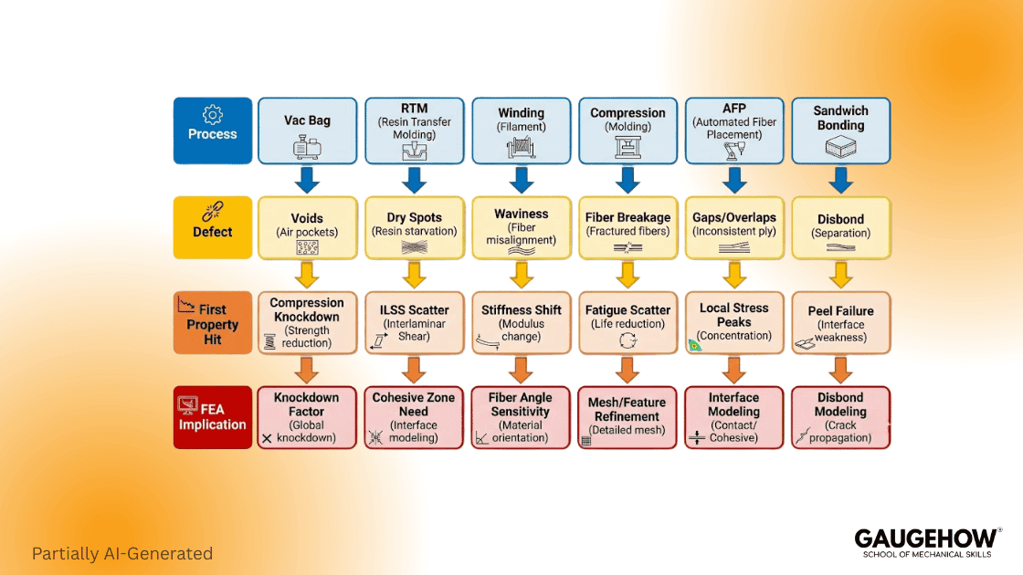
Process | Typical Defect | First Property Hit |
Hand layup, vacuum bag | Voids, resin-rich zones, poor wet out | Compression strength, ILSS scatter |
RTM, infusion | Dry spots, race tracking, porosity bands | Strength variability, delamination starts |
Filament winding | Fiber angle error, waviness | Stiffness shift, burst margin loss |
Compression molding | Fiber breakage, orientation drift | Fatigue scatter, flexural knockdowns |
Automated fiber placement | Gaps, overlaps, and steering waviness | Local stress peaks, early damage at features |
Sandwich bonding | Disbonds, crushed core, weak adhesive | Peel strength loss, face wrinkling risk |
Composites fail like structures, not like monolithic materials. That is why process control shows up in allowables and in scatter.
Properties With Test-Based Anchors
Carbon fiber density is commonly cited as around 1.6 to 2.0 g/cm³. E-glass density is commonly listed around 2.55 g/cm³ in typical property tables. Those numbers are not laminate density, but they explain why designers keep talking about specific stiffness.
Property Anchors Table
Property Anchor | Typical Value Or Range | What It Changes First | Test Basis Or Source |
Vacuum consolidation pressure ceiling | 14.7 psi max at sea level | Void risk, fiber volume ceiling, compression knockdowns | WEST SYSTEM vacuum bagging manual (westsystem.com) |
Practical vacuum clamp range | about 6 to 12.5 psi | Realistic consolidation and thickness control | WEST SYSTEM manual guidance (westsystem.com) |
Low-pressure processing reference | 85 psi (6 bar) minimum | Consolidation, void suppression, and thickness stability | Hexcel note referencing 85 psi (6 bar) (hexcel.com) |
“High-performance” fiber volume signal | about 60% fiber volume used in sizing assumptions | Stiffness and strength expectations, knockdown sensitivity | NASA NTRS example using 60% fiber volume in sizing (NASA Technical Reports Server) |
Tensile coupon baseline | D3039 establishes in-plane tensile properties | Modulus, strength, strain, and Poisson’s ratio basis | ASTM D3039 scope (ASTM International | ASTM) |
Advantages And Limitations
Advantages
You can tailor stiffness and strength by orientation.
Corrosion resistance can be strong in many environments.
Mass efficiency can be excellent when stiffness limits dominate.
Limitations
Directionality raises design and QC difficulty.
Damage can be hidden, especially delamination.
Properties scatter when process control slips.
Repair and recycling constraints can be real project risks.
Composite Decisions For FEA
FEA is where composites punish shortcuts because the material is not a single isotropic card. A laminate is “material plus architecture.”
Two failure modes drive most bad models:
The wrong axes carry the load
The layup definition does not match the part
Selection Gate Workflow
Loads And Environment Defined?
-> Matrix Family Chosen (PMC, MMC, CMC, Carbon-Carbon)
-> Reinforcement Form Chosen (UD, Woven, Chopped, Particulate, Sandwich)
-> Process Chosen (Vac Bag, RTM, Press, AFP, Winding)
-> Defect Risks Named (Voids, Waviness, Resin-Rich, Dry Spots)
-> Test Basis Locked (Laminate Form + Standard)
-> FEA Inputs Locked (Ply Axes + Layup + Criterion + Checks)
The No-Guesswork Material Card Pack
Must Have
Layup definition: ply angles, thickness, and stacking order.
Orientation definition that matches CAD, mesh, and solver axes.
Density and elastic constants tied to a real laminate source.
Strength allowables plus the criterion you will report.
A test basis statement, often starting with ASTM D3039, in tension.
Nice To Have
Moisture and temperature knockdowns.
Notes on expected void content or fiber waviness.
A short shortlist metric using specific strength and specific modulus.
Do Not Fake
Fiber angles in critical load paths.
Perfect bonding where interfaces are known weak points.
Isotropic shortcuts unless validation proves equivalence.
Conclusion
Composite materials are defined by both constituents and structure. Classic examples like concrete and plywood satisfy the head term, while laminates and sandwich panels cover modern engineering practice. When analysis starts, lock axes, layup, and test basis early. That is what turns composites from confusing to predictable.
FAQ
What Is A Composite Material?
A composite is made from two or more constituents with dissimilar properties that remain distinct in the finished structure, creatinga combined performance that differs from each constituent alone.
Is Concrete A Composite Material?
Yes. Concrete and reinforced concrete are commonly cited composite examples because a cementitious matrix and reinforcement work together while remaining distinct.
Is Fiberglass A Composite Material?
Yes. Fiberglass is a fiber-reinforced composite where glass fibers carry the load and a polymer matrix binds and transfers the load.
Is Wood A Composite Material?
Many engineered woods are composites in practice. Plywood is a clear example because layered veneers act together while remaining distinct layers.
How Are Composite Materials Made?
Common methods include layup with vacuum consolidation, filament winding, pultrusion, resin transfer molding, compression molding, and automated fiber placement.
References
Encyclopaedia Britannica, composite material definition and overview.
Wikipedia, “Composite material” overview, examples, laminates.
ASTM D3039/D3039M, tensile properties test method scope.
CompositesWorld, vacuum bagging compaction pressure limit.
WEST SYSTEM, Vacuum Bagging Techniques manual and pressure notes.
Hexcel, prepreg processing note referencing 85 psi (6 bar).
Toray CMA, 3900 prepreg system datasheet, laminate density value.
NASA NTRS, examples referencing 60% fiber volume in laminates.
Verification Sources
Your original baseline draft PDF.
Vacuum bagging compaction ceiling around 14.7 psi at sea level. (compositesworld.com)
Hexcel reference showing 85 psi, about 6 bar, in a recommended cycle note. (hexcel.com)
Toray CMA 3900 datasheet listing laminate density 1.54 g/cc. (Toray Composite Materials America, Inc.)
NASA NTRS example referencing 60% fiber volume in UD laminates. (NASA Technical Reports Server)
Britannica composite material definition. (Encyclopedia Britannica)
Wikipedia composite material overview and “remain separate” distinction. (Wikipedia)
ASTM D3039 scope for in-plane tensile properties. (astm.org)
CAD-CAM-CAE Work Platform
Find or Post CAD, CAM and CAE freelance projects, full-time jobs and Internships.
GaugeHow is the platform built for core engineering work. Whether you need a freelancer for a CAD project, a full-time hire, or an engineering intern,post it here and get matched with the right person.
Our Courses
Complete Course Library
Access to 40+ courses covering various fields like Design, Simulation, Quality, Manufacturing, Robotics, and more.


