Composite Materials in FEA: Layup, Failure, Modeling Guide


Deepak S Choudhary
A composite model does not fail in postprocessing. It fails earlier because ply axes are unclear, allowables do not match the test basis, or the failure metric misses the physics. This guide demonstrates how to define layup cleanly, select a failure approach, and validate the model with rapid verification gates.
What You Will Learn: Layup definition, ply axes, failure criteria choice, verification gates.
What You Will Not Do: Generic history and long type lists with no modeling decisions.
Who It Is For: FEA engineers, design reviewers, simulation leads.
Definition + FEA Translation
1. Definition: A composite material: two or more distinct materials combined to outperform the constituents in targeted ways.
2. Made of: A matrix that bonds and transfers load, plus reinforcement that carries most tensile load.
3. Why FEA Is Different: stiffness is directional, and damage is mode-specific rather than a single yield point.
4. One-Line Decision: If you cannot define the ply axes, stop and fix that first.
Definition And FEA Translation
You are not modeling “a material.” You are modeling a laminate manufacturing instruction. In composite materials FEA, that translation is the work. Inside the solver, it becomes a stiffness field, a strength field, and a set of damage checks. That translation is why many otherwise clean models get rejected during design review.
A laminate works because fibers carry load along their axis, and the matrix carries transverse shear and compressive support. That split changes your inputs. You need properties in the fiber direction, the transverse direction, and the in-plane shear direction. Strength allowables must also separate tension and compression. The same split changes outputs. Fiber tension, matrix shear, and crushing do not behave the same under one global load.
ASTM D3039 is often used to characterizethe in-plane tensile response of fiber-reinforced polymer laminates. It reports modulus, Poisson’s ratio, and tensile strength. Align model assumptions with the test basis you cite. Avoid mixing vendor tables and handbook numbers unless you state conditions and knockdowns.
Composite Layup And Ply Axes
The composite layup is the physical definition of the laminate: ply sequence, ply thickness, ply material, and ply angle. Your model also needs an angle reference rule. “0 degrees” has no meaning unless it is anchored to geometry or a datum.
Angle reference is where real parts break the textbook. Cutouts, tapered plies, and wrapped surfaces create local coordinate fields that can flip if you rely on an automatic surface normal. An axis flip is not a cosmetic issue. It changes the membrane and bending stiffness, and it can move a predicted hot spot to the wrong side of a joint.
Layup Setup That Survives Review
Start by locking the thickness and reference surface, because offsets create artificial peel near constraints. Define the angle rule in one sentence, such as “0 follows the projected longest edge on the mid-surface.” Finish by verifying the axis field is continuous across trims and splits.
Reviewers will ask for proof, not intent. Run a sensitivity where you rotate the fiber direction in the hot zone by a small angle and confirm the response shifts smoothly. Discontinuous jumps usually mean the axis field is tied to a geometric feature that changes sign.
Numbers You Can Sanity-Check
Build a four-ply laminate, apply a simple in-plane load, and run two jobs before you trust anything. Case A aligns the hot-zone fiber direction with the load path. Next, in Case B, rotate the local axes by 10 degrees only in the hot zone.
Now compare axial strain at a gauge line, reaction closure, and the location of peak failure index. Stable models show a modest stiffness shift and a hot zone that stays put. Fragile setups show a large stiffness shift or a hot zone that jumps. This behavior is usually an axis discontinuity, not “nonlinear behavior.” MIT’s laminated plate notes show why this sensitivity is expected, because orientation changes laminate stiffness through the ABD matrices.
As a second check, the same micro-test is also a good cfrp sanity gate when you are validating a new layup toolchain or new preprocessor settings.
Material Data And Allowables
Material data errors tend to hide behind clean contours. The biggest drivers are mixed test bases, unknown consolidation quality, and missing strength allowables in the transverse and shear directions.
Minimum ply cards should include E1, E2, G12, ν12, density, and in-plane shear strength. Add strength allowables in tension and compression along the fiber and transverse. This is the level of information you need to run a defensible first pass and to decide whether delamination needs a separate model.
Types You Actually Model, Not A Catalog
Most structural simulation work sits in polymer matrix composites. In practice, this architecture dominates practical laminates and has the richest public test basis.
Data availability still varies. gfrp is common in cost-sensitive structures, while carbon fiber composites often come with tighter test documentation in regulated industries. Natural fiber composites can be viable in noncritical structures, but variability in fiber quality and moisture state is a first-order uncertainty you must call out. With natural fiber composites, bake that variability into your knockdowns and do not present single-number margins without a sensitivity band.
If a stakeholder asks, “What is a composite material?” they usually mean, “What controls performance?” In analysis, the answer is the ply card quality and the process route, because those control voids, thickness, and knockdowns.
Manufacturing Inputs That Change FEA Results
Manufacturing pressure is not a footnote. Vacuum bagging uses atmospheric pressure as a clamp. Many manuals describe the clamp level around 14.7 psi, which is roughly one atmosphere at sea level.
For many industrial studies of polymer matrix composites, vacuum bagging is the default assumption, so call it out when the part was actually autoclaved or press-cured.
Autoclave processing increases consolidation pressure further. Literature describes consolidation pressure on the order of 6 to 8 bar for low-void, well-consolidated laminates.
These details matter because consolidation shifts thickness, fiber volume fraction, and defect population, which then shifts stiffness and strength. If you do not know the process, state that uncertainty and run sensitivity on thickness and shear allowables instead of presenting a single “precise” reserve factor.
Strength And Stiffness Per Mass
Weight-driven programs almost always argue in ratios. Specific strength captures how much load capability you buy per unit mass. For stiffness, specific modulus captures how much stiffness you buy per unit mass. Keyword research data shows that strength to weight ratio is a common search phrasing for the same idea.
Stiffness-limited designs should report deflection and strain first, then margins. Strength-limited designs should report reserve factors by ply and by failure mode, along with which allowables drove the minimum margin.
Workflow Card And Verification Policy
Good composite analysis reads like a standard operating procedure. The point is not to be verbose. Instead, the goal is to be rebuildable and reviewable.
Workflow Card (7 Steps)
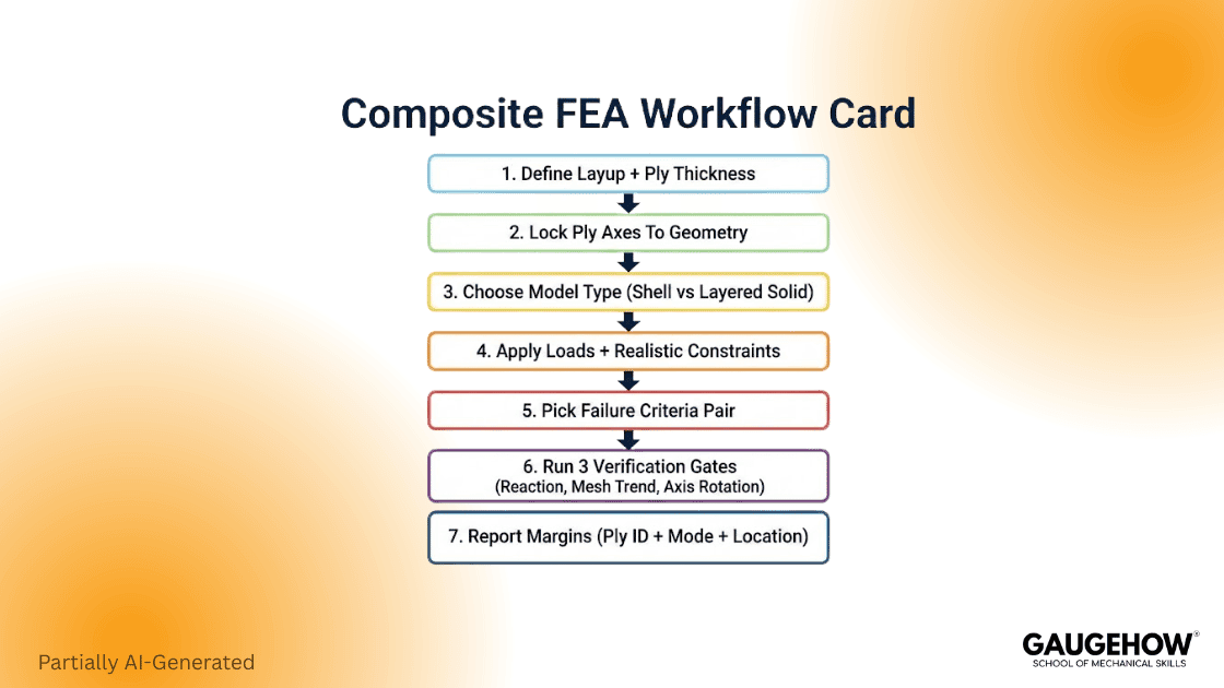
Define composite layup stack and ply thickness.
Lock the ply axes to the geometry with a documented rule.
Choose element strategy: shell, layered solid, or mixed.
Apply loads with realistic constraints and contact where needed.
Select composite failure criteria that match the load state and the data.
Run three verification gates: reaction closure, hot-zone mesh trend, and axis rotation sensitivity.
Report margins with ply ID, failure mode, and coordinate location.
How We Think Differently
We treat the axis field and the data basis as part of the model, not as setup details. That separation between “screening models” and “review models” keeps results compared at the right fidelity. This framing keeps teams from arguing about decimals when the inputs are still uncertain.
Non-Negotiable Model Verification Policy
1. Reaction Closure: Reactions match applied loads within an engineering tolerance.
2. Hot-Zone Mesh Trend: Peak strain and failure index converge in the hot zone with local refinement.
3. Ply Axis Rotation Sensitivity: A small axis rotation changes results smoothly, not abruptly.
4. Margin Reporting: Every margin is tagged with ply ID, mode, and location.
Composite Failure Criteria And Modeling Choosers
Composite failure criteria selection is a design decision, not a checkbox. Each family encodes assumptions about which stress components drive damage. Most do not directly predict delamination unless you add a cohesive or interlaminar model.
Commercial workflows often expose the same core families. For example, ANSYS ACP documents Tsai style criteria, Hashin, Puck style options, and related families for reinforced materials.
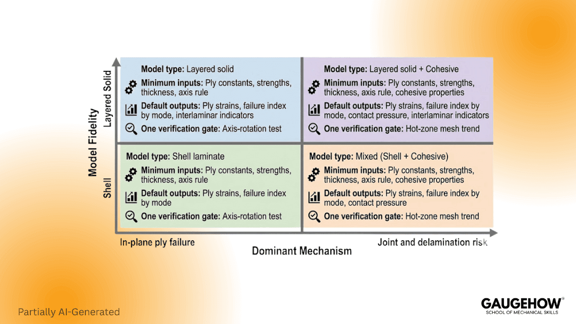
Quadrant | Model Type | Required Inputs | Default Outputs | One Verification Gate |
Fast Screening | Shell laminate | Ply card, thickness, axis rule | In-plane strain, ply margins | Axis rotation test |
Hot-Spot Review | Refined shell plus local solid | Local offsets, joint details | Contact pressure, hot-zone strain | Hot-zone mesh trend |
Through-Thickness Risk | Layered solid | Full orthotropic set, offsets | Out-of-plane stress indicators | Boundary stiffness sweep |
Damage Study | Cohesive or progressive | Fracture energy, traction laws | Separation, damage variables | Energy balance check |
Failure Criteria Selection Table
Criterion Family | Best For | What It Misses | What To Verify First |
Max Stress / Max Strain | Clear allowables, simple load states | Interaction effects | Ply axis definition |
Tsai-Wu / Tsai-Hill | Mixed stress states with calibrated coefficients | Mode separation | Test basis consistency |
Hashin | Fiber and matrix mode separation in UD plies | Delamination without an extra model | Stress state mapping |
Puck | Inter-fiber failure logic and nuanced matrix modes | Needs parameters and care | Parameter sensitivity |
Hashin’s unidirectional work is a standard reference for mode-based failure. It explicitly separates fiber and matrix modes, which helps when you need mechanism clarity.
Joints And Load Introduction
Bolts, holes, and bondlines introduce load, and they also introduce failure modes your global laminate can hide. Bearing at a fastener, bypass tension along the net section, and peel under a clamp pad can coexist in the same few millimeters. Shells can be sufficient for global sizing. Layered solids earn their keep when you must defend peel and through-thickness shear near constraints.
Joint realism is also material dependent. Many teams see acceptable global strains in cfrp. The same teams then miss a matrix-driven local failure at the load introduction feature because out-of-plane effects were filtered by the model choice. Similar issues show up in gfrp attachments where bearing and peel couple. Metal inserts and thick washers can also drive localized contact pressure.
FAQ
What Is The Difference Between A Lamina And A Laminate?
Lamina means a single ply with one material axis definition. Laminate means a stacked set of plies where stiffness and strength come from the sequence, orientation, and thickness distribution.
When Should I Use Shells Versus Layered Solids?
Shell laminates work well for global stiffness, load paths, and early sizing. Switch to layered solids locally where you need through-thickness stress, peel, or credible joint behavior.
How Do I Choose Between Tsai-Wu And Hashin?
Hashin fits when you need fiber and matrix modes separated, and you have unidirectional ply data. Tsai-Wu fits when you have calibrated interaction terms and a mixed stress state, then validate it against test or prior allowables.
What Are The Fastest Checks Before I Trust Results?
Confirm reaction closure, then run a hot-zone mesh trend, then run a ply axis rotation sensitivity check. If any of these fail, do not interpret failure contours.
What Is A Composite Material?
In analysis terms, it is a matrix plus reinforcement system where the reinforcement carries most tensile load and the matrix bonds and transfers load. That structure is why the part is directional and why failure is mode-driven.
Reference
MIT OpenCourseWare, “Laminated Composite Plates” (ABD matrices, laminate stiffness)
Z. Hashin, “Failure Criteria for Unidirectional Fiber Composites” (1980), ASME Journal of Applied Mechanics
ANSYS Help, ACP, “Failure Criteria for Reinforced Materials” (Tsai, Hashin, Puck families)
ASTM D3039/D3039M, “Standard Test Method for Tensile Properties of Polymer Matrix Composite Materials” (official standard page)
WEST SYSTEM, “Vacuum Bagging Techniques” manual (vacuum bagging practice and pressure basics)
ScienceDirect (Composites Part A), Liu, et al. (2021), autoclave pressure 6–8 bar context
Conclusion
Composite Materials succeed in FEA when the model is treated like a controlled translation. The layup must be explicit, the axis field must be continuous, and the data basis must match the allowables.
If you track specific strength and strength-to-weight ratio for lightweight decisions, and you verify stiffness with specific modulus, debates turn into repeatable calls. That discipline also reduces surprises when carbon fiber composites move from CAD to production.
CAD-CAM-CAE Work Platform
Find or Post CAD, CAM and CAE freelance projects, full-time jobs and Internships.
GaugeHow is the platform built for core engineering work. Whether you need a freelancer for a CAD project, a full-time hire, or an engineering intern,post it here and get matched with the right person.
Our Courses
Complete Course Library
Access to 40+ courses covering various fields like Design, Simulation, Quality, Manufacturing, Robotics, and more.


