Computer-Aided Engineering (CAE): Process, Checks, Tools


Deepak S Choudhary
CAE uses computers to model, simulate, and evaluate how a product behaves under real loads and constraints before you cut metal. Done well, it reduces iteration risk, exposes weak assumptions early, and produces a defensible engineering decision. This guide shows the CAE cycle, scope, and the minimum credibility checks.
What Is CAE?
Computer-aided engineering (CAE) uses computers to model and analyze the response of a product subjected to external loads and constraints, so you can evaluate performance, reliability, and safety before physical build. In practice, CAE is not “software output.” It is an engineering method for turning requirements into decisions with quantified risk.
A useful way to frame CAE is as part of the broader engineering process that converts needs into functional requirements, explores a solution space, analyzes candidates, then selects and validates an optimal solution.
That framing matters because it forces you to treat simulation as evidence in a decision chain, not as a picture generator.
CAE Phases
Most CAE work follows a tight loop with three phases: Pre-processing → Solver → Post-processing. Siemens and TWI both describe CAE as a process that comprises preprocessing, solving, and postprocessing, where loads and constraints are defined up front, physics is solved, and then results are reviewed.
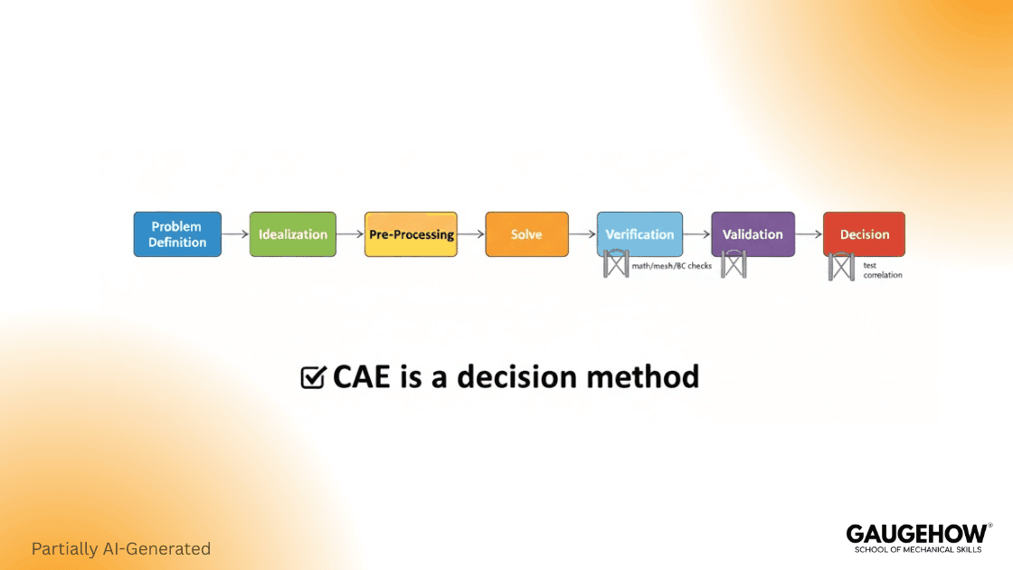
CAE Cycle In Three Steps
Pre-processing: lock the decision, simplify CAD, assign behavior, BCs, interfaces, mesh budget.
Solver: accept results only after convergence, using a physics formulation and tolerances.
Post-processing: extract decision outputs, validate reactions and energy, document limits, drive next loop.
If you only remember one rule, remember this: the solver will happily produce a result even when your boundary conditions are wrong. Most CAE failures are not “solver bugs.” They are modeling choices that were never validated.
CAE Vs CAD Vs CAM
CAD locks shape and specs. CAE verifies that intent under real loads before release. CAM then outputs NC paths for the CNC, keeping scrap within your target rate.
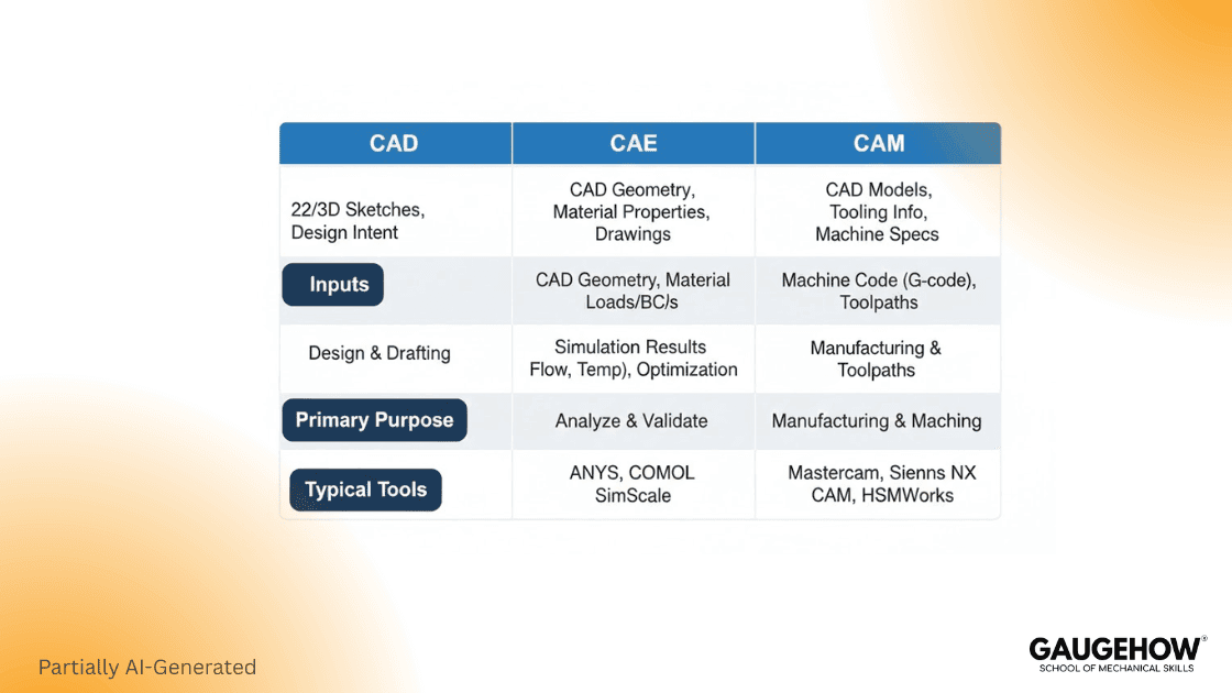
Tool | Purpose | Typical Inputs | Typical Outputs | Decision Purpose |
CAD | Create and modify the design definition | Requirements, interfaces, dimensions | 2D drawings, 3D models, BOM-ready geometry | “Lock the product definition.” |
CAE | Predict behavior under physics | CAD model, materials, loads, constraints | Stress, deflection, temperature, flow, modes | “Prove performance under operating loads.” |
CAM | Produce manufacturing instructions | CAD geometry, tools, feeds, setups | Toolpaths, G-code, process plans | “Plan the manufacturing path.” |
CAD→CAE→CAM | Integrated cycle | Design data plus test and process constraints | Verified design plus manufacturable plan | “Release only after margin and checks pass.” |
Engineering Process From Requirements To Decisions
A practical engineering process converts customer needs into something buildable and testable. One concise definition says an engineering process is to “convert customers’ needs into a physical product or system.”
That conversion only works when requirements become model inputs you can defend.
Step 1: Identify Requirements And Define The Design Problem
Start with customers’ requirements (CRs), operating environment, standards, and performance metrics. Then define the design problem in terms of goals and constraints. A crisp way to say it is: the first step is to formulate the design problem with clear CRs, objectives, and constraints.
In practice, you should write requirements in measurable form:
Load, speed, pressure, temperature
Life targets and allowable deflection
Safety factors, codes, and test conditions
Manufacturing and packaging constraints
Step 2: Define The Solution Space And Design Variables
A strong definition to anchor here is: “A solution space consists of all possible design options” that can meet requirements and constraints.
So you define design variables (DVs), their allowable ranges, and what counts as feasible. That is where you decide which dimensions can change, which materials are allowed, and which interfaces are frozen.
Step 3: Run Design Analysis And Use It To Choose Better Options
Design analysis is not only running a solver. It uses physics to evaluate whether an option meets constraints and how well it performs against your criteria. A compact line worth keeping in mind is: design analysis is used to “model the behaviors” and decide whether it meets constraints and performance targets.
Step 4: Design Synthesis, Then Verification And Validation
Design synthesis involves comparing and selecting alternatives. A practical description is that it includes selecting a baseline candidate, exploring better ones, and defining termination criteria for the search.
Then comes Verification, Validation, and Implementation. Verification checks whether the equations are solved correctly. Validation ensures that the model accurately represents reality for its intended use. This distinction is a standard framing in engineering V&V practice. ASME
FR To DV Traceability That Engineers Can Audit
A simple way to avoid “simulation theater” is to keep a traceable chain:
FR (what must be true) → DV (what you can change) → Model Evidence (what you will check)
Example:
FR: “Bracket tip deflection ≤ 0.25 mm.”
DV: thickness, rib height, bolt spacing
Evidence: deflection at a defined node set under a defined load case, plus a mesh independence check
This single chain prevents two common failures: optimizing the wrong thing and arguing about results without a shared testable definition.
What CAE Includes And CAE Software Examples
What CAE Includes
CAE is an umbrella that commonly includes finite element analysis (FEA), computational fluid dynamics (CFD), multibody dynamics, and optimization, depending on the product and the decision you need to make. (Siemens Digital Industries Software)
CAE Software Examples
Use this as a quick orientation, not a buying guide.
ANSYS Mechanical: structural FEA for stress, deflection, fatigue workflows.
ANSYS Fluent: CFD for flow, heat transfer, and turbulence modeling.
Abaqus: nonlinear mechanics, contact, large deformation, materials.
MSC Nastran: linear dynamics, aerospace-grade structural solvers.
LS-DYNA: explicit dynamics for impact, crash, and forming.
STAR-CCM+: CFD with strong meshing and multiphysics options.
MSC Adams: multibody dynamics for mechanisms and joint loads.
Simcenter (NX/3D): CAE environment for pre- and post plus solvers. (Siemens Digital Industries Software)
COMSOL: multiphysics coupling with PDE-based workflows.
Worked Micro-Examples
Example 1: Bracket Under Load (Two Decisions)
Requirement: bracket tip deflection ≤ 0.25 mm, and von Mises stress gives a safety factor ≥ 1.25 against yield.
Load Case: 500 N downward at the tip.
Boundary Choice: bolt holes constrained with realistic stiffness, not fully fixed faces.
Key Output: displacement at tip, peak stress at fillets, reactions at bolts.
Numeric Pass/Fail Output
(Values below are illustrative, so the decision logic is clear. Your project numbers will differ.)
Metric | Limit | CAE Result | Pass/Fail |
Tip Deflection | ≤ 0.25 mm | 0.18 mm | Pass |
Peak von Mises Stress | ≤ 200 MPa | 175 MPa | Pass |
Safety Factor (Yield/Stress) | ≥ 1.25 | 1.43 | Pass |
Decision 1: If deflection fails, stiffness drives the redesign (thickness, rib, material).
Decision 2: If stress fails, local geometry drives the redesign (fillet radius, notch relief, load path).
Two Common Mistakes
One mistake is over-constraining the bracket like a perfect clamp, which can underpredict deflection and shift stresses. Another mistake is using a default steel with an unknown yield or ignoring contact at the joint, which can hide bolt load transfer and produce misleading peaks.
Example 2: Thermal Mini-Case
Requirement: The electronics enclosure must keep the hotspot ≤ 85 °C at 25 °C ambient.
Model: conduction through base plate plus convection boundary on fins.
Decision input: assume a 12 W heat source at the hotspot.
Output: predicted hotspot 82 °C, so it passes with a margin.
Risk check: if the convection coefficient is guessed, run a sensitivity sweep.
If the hotspot rises above 85 °C, increase the fin area or improve the interface resistance.
Error And Credibility Checks
Engineers trust CAE when it is hard to fool. These checks are fast, and they catch most wrong models.
Credibility Checklist
Boundary Condition Realism: Does the constraint represent a physical interface or a convenience clamp?
Material Property Realism: Are you using the correct elastic modulus, yield model, and temperature dependence?
Contact Assumptions: Do contacts transmit compression only, stick-slip friction, or are they bonded?
Mesh Independence Concept: Does refining the mesh change your key output meaningfully?
Sensitivity Check: Which input dominates the output, and does that match engineering intuition?
Verification and validation language matters here because it separates “solver correctness” from “model usefulness.” NASA-STD-7009B
Failure Modes Table
Symptom | Likely Cause | First Fix | Where It Shows Up |
Stress is infinite at a corner | Singular load or sharp geometry | Use distributed loads and realistic fillets | Post-processing hot spots |
Deflection is suspiciously low | Over-constraint | Replace fixed faces with joints, bolts, or contact | Boundary conditions |
Results change a lot with mesh | Under-resolved gradients | Refine mesh near fillets, contacts, and thin regions | Mesh and convergence |
Contact “chatter” or nonconvergence | Stiff contact setup | Adjust contact stiffness, friction, and step controls | Solver iteration log |
Loads look wrong at supports | Bad load path assumption | Check reactions and free-body balance | Reactions and constraints |
Conclusion
CAE is a decision tool when it is connected to requirements, built on realistic boundary conditions, and supported by minimum verification checks. Use the three-phase cycle, keep the scope clear, and document the deliverables like an engineering record.
When you do that, CAE reduces iteration risk and improves design confidence without replacing real testing.
FAQ
1) What is the main purpose of CAE?
Use CAE to forecast response under load and boundary limits, then release only if the margin-of-safety meets your target KPI.
2) What are the three phases of CAE?
Pre-processing, solving, and post-processing.
3) Is CAE the same as FEA?
No. FEA is a CAE subset. CAE also covers CFD, multibody motion, and optimization, with different solvers.
4) What makes a CAE result credible?
Credible results balance forces, keep units consistent, show mesh convergence and sensitivity stability, and leave a traceable V&V review log.
5) What is mesh convergence in simple terms?
It is showing that refining the mesh does not materially change the quantity you care about, so the result is not a mesh artifact. (NAFEMS)
6) What Is The Difference Between Verification And Validation?
Verification checks whether the model is solved correctly for the equations you wrote (numerics, mesh, solver setup). Validation checks whether those equations and assumptions represent the real system well enough for the decision, using test or benchmark evidence.
7) What Is Validation?
Validation is the process of comparing simulation predictions against trusted physical data to confirm the model represents reality for the intended use case, within an acceptable error margin.
CAD-CAM-CAE Work Platform
Find or Post CAD, CAM and CAE freelance projects, full-time jobs and Internships.
GaugeHow is the platform built for core engineering work. Whether you need a freelancer for a CAD project, a full-time hire, or an engineering intern,post it here and get matched with the right person.
Our Courses
Complete Course Library
Access to 40+ courses covering various fields like Design, Simulation, Quality, Manufacturing, Robotics, and more.


