Design Analysis Methodologies: Methods, FEA, FDM, BEM


Deepak S Choudhary
Design analysis methodologies explain how engineers predict system behavior from physics before committing to building.
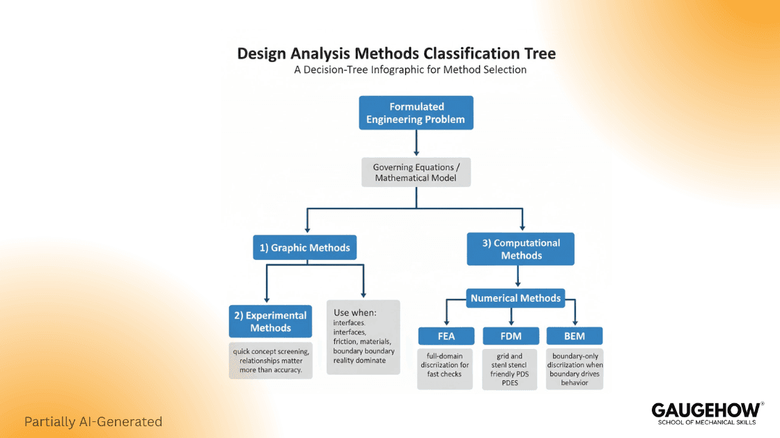
The workflow starts with governing equations, then selects a method family: Graphic Methods, Experimental Methods, or Computational Methods. Computational work splits into Analytical Methods and Numerical Methods, including FEA, FDM, and BEM. This page gives clean definitions and a tight comparison.
Design analysis starts from physics, not software. A product or system responds to loads and constraints according to scientific principles that can be represented by governing equations.
In solids, responses under external loads can be represented through compatibility relations, strain-displacement relations, and the equations of motion.
Once a mathematical model is formulated, different engineering methods can be used to analyze the system.
Credibility Box
NASA reports that during design, only about 15% of costs might be expended, but the design can commit about 75% of the life cycle costs. NASA+1
A Design Society ICED study found that early design decisions required thirteen times more rework on average, and early phase decisions accounted for 86% of total potential rework cost in the projects analyzed. Design Society+1
The three method families below are the standard entry point, and the rest of the page stays inside that tree.
Graphic Methods
“A graphic method uses the drawing tools to define the relations of inputs and outputs of a system graphically.”
Graphic methods are best when you need visibility first. They let you see relationships early, especially when the system is simple enough that the picture is not hiding critical physics.
In practice, you use them to reduce uncertainty in concept selection, then you move to stronger evidence when decisions become expensive.
Use Graphic Methods when:
You are screening concepts and need fast direction
The problem is simple, and the goal is insight, not precision
Avoid them when: Geometry, contact, or coupled physics dominate behavior
Experimental Methods
“An experimental method studies the relations of inputs and outputs of a system experimentally.”
Experimental methods are strongest when reality is hard to model. They become essential when contacts, friction, materials, or boundary interfaces control the outcome, and you cannot defend assumptions confidently.
The practical limitation is the scaling cost because each additional variable increases the test burden.
Use Experimental Methods when:
Unknown physical effects dominate the decision
You must anchor results to measured system behavior
Expect these constraints:
Experiments are conducted on a physical system and are often later implemented
Fixing design errors late has a high cost
Computational Methods
“A computational method uses computer models to simulate system behaviors.”
Computational methods are chosen when you need to predict behavior across many design options, or when physical testing is too slow or too expensive for early iteration.
Their value is coverage and repeatability. Their risk is false certainty if the model setup is not defensible.
Comparison Of Different Design Analysis Methods
Method | What It Does | Best Fit | Primary Limit |
Graphic | Defines input-output relations graphically | Simple problems, high visibility | Preliminary, limited complexity |
Experimental | Models input-output relations experimentally | Physical truth, hard-to-model effects | Cost and scaling with variables |
Computation-al | Simulates behaviors using computer models | Many options, complex systems | Depends on model fidelity |
Analytical | Obtains system outputs analytically | Some simple problems with explicit outputs | Limited applicability |
Numerical | Obtains outputs numerically by simulation | High complexity and uncertainty | Requires discretization choices |
Computational Methods In Practice
Computational methods are further classified into analytical methods and numerical methods.
Analytical Methods
“An analytical method uses analytical models to represent the relations of system inputs and outputs.”
You use analytical methods when the problem is simple enough that outputs can be obtained explicitly. They are ideal for fast checks and for bounding results.
Numerical Methods
“A numerical method uses numerical models to represent the relations of system inputs and outputs.”
“System outputs are obtained numerically by computer simulation.”
Numerical methods are widely used when complexity and uncertainty make other methods impractical. That is the real reason they dominate modern engineering analysis.
Numerical Methods Mastery
Numerical methods are widely used to analyze systems with high complexity and uncertainties, which cannot be tackled with graphic methods, experimental methods, or analytical methods.
Numerical methods have become the default CAE tools for a number of reasons:
Modern products or systems have become so complex that other design analysis methods cannot thoroughly evaluate their performance.
In contrast to experimental methods, numerical methods can predict system behavior without physical prototyping. This reduces development cost, shortens design time, and allows engineers to compare a large number of design options for optimization.
Cutting-edge CAD and CAE tools are available, so engineers can solve a wide range of engineering problems without sophisticated training.
Many numerical methods are available, and they generally use the divide and conquer strategy to deal with the generality and complexity of different engineering problems.
Within this scope, the standard set is FEA, FDM, and BEM.
FEA, FDM, And BEM Comparison
Finite Element Analysis (FEA), Finite Difference Method (FDM), and Boundary Element Method (BEM) are numerical methods used to solve engineering problems by breaking a continuous mathematical model into a form that a computer can solve.
In real design work, they follow a divide and conquer strategy so complex geometry and physics can be handled with practical accuracy.
Key Differences
FEA vs FDM (How Derivatives Are Approximated): In FEA, derivatives are evaluated through integration over elements. In FDM, derivatives are evaluated using finite differences at discrete points.
FEA vs BEM (Where the Domain Is Discretized): An FEA model places elements and nodes throughout the entire domain. A BEM model places elements and nodes only on the domain boundaries.
What This Means Operationally: FEA is a general-purpose workhorse because it represents the full field inside the part. FDM is conceptually direct because it approximates derivatives point to point. BEM can reduce modeling effort when boundary behavior drives the response because only boundaries are discretized
The right choice comes down to what you need to represent. If internal stress and temperature fields inside the domain drive failure, full domain discretization favors FEA.
If the formulation is easier on discrete points, FDM can be effective. If boundary effects dominate and the formulation supports it, BEM can be an efficient option without meshing the full volume.
Hard Boundaries
FDM
Use when the domain maps cleanly to structured grids and your PDE form maps cleanly to point stencils.
Avoid when geometry is irregular, boundaries are complex, or you need unstructured discretization without losing meaning at boundary features.
BEM
Use when boundary effects dominate, and the formulation supports boundary-only discretization.
Avoid when the problem class or physics does not support boundary-only formulations cleanly, or when you need broad generality across interior behavior. Stanford University+1
FEA
Use when internal stress or temperature fields inside the domain drive failure, because full domain discretization is the point.
Avoid when a boundary-only formulation is valid, and the interior is not the decision driver, because you may be paying for interior resolution you do not need.
Numeric Pass Fail Micro Example
The governing model is a structural load case where geometry includes fillets and holes, so closed-form results are not defensible as the final decision. That pushes you to Computational Methods, then Numerical Methods, and the geometry rules out structured grid assumptions, so you pick FEA, not FDM.
Output Check | Requirement | Predicted Result | Pass |
Max Deflection | ≤ 0.50 mm | 0.62 mm | No |
Max Stress | ≤ 250 MPa | 310 MPa | No |
Factor Of Safety | ≥ 1.50 | 0.81 | No |
Decision: The method selection is correct, and the design fails the requirement, so the next step is to change stiffness, load path, or material, then rerun the same defensible workflow.
Misuse Warnings
Graphic Methods: hides coupling, leads to false simplicity.
Experimental Methods: variable scaling tests the test burden fast.
Computational Methods: weak setup creates false certainty.
FAQ
1) What Are Design Analysis Methodologies
They are engineering methods used to analyze a product or system after a mathematical model is formulated, including graphic, experimental, and computational methods.
2) What Is A Computational Method
“A computational method uses computer models to simulate system behaviors.”
3) What Is The Difference Between Analytical And Numerical Methods
Analytical methods obtain outputs explicitly for some simple problems, while numerical methods obtain outputs numerically by computer simulation.
4) How Does FEA Differ From FDM
In the source definition, derivatives are evaluated by integration in FEA and by finite differences in FDM.
5) How Does FEA Differ From BEM
In the source definition, FEA uses elements and nodes in the entire domain, while BEM uses elements and nodes only on the boundaries.
Conclusion
Design analysis methodologies start with governing equations and a formulated model. From there, you choose a method family that matches the decision risk and the system complexity. Graphic Methods give early visibility, Experimental Methods anchor real behavior, and Computational Methods scale to complex systems and many design options.
Inside computational work, the analytical versus numerical split is the key fork. Numerical methods then break into FEA, FDM, and BEM, and the correct choice depends on whether the problem is best treated as a domain discretization or a boundary discretization.
References
Zhuming Bi, First-Time-Right for Designs of Products (public PDF copy of the same chapter family). (Springer Link)
Cadence System Analysis, boundary element vs finite element overview. (Cadence System Analysis)
WIT Press, boundary-type vs domain-type method discussion (BEM vs FEM framing). (WIT Press)
Wikipedia, Finite element method overview and context. (Wikipedia)
CAD-CAM-CAE Work Platform
Find or Post CAD, CAM and CAE freelance projects, full-time jobs and Internships.
GaugeHow is the platform built for core engineering work. Whether you need a freelancer for a CAD project, a full-time hire, or an engineering intern,post it here and get matched with the right person.
Our Courses
Complete Course Library
Access to 40+ courses covering various fields like Design, Simulation, Quality, Manufacturing, Robotics, and more.


