FEA Modeling: Step-by-Step Workflow And Best Practices


Deepak S Choudhary
FEA modeling is the disciplined conversion of a real engineering problem into a solvable finite element model with explicit assumptions. You lock inputs, outputs, and parameters first, then build elements, apply boundary conditions and loads, and finally prove result stability with mesh convergence and sanity checks.
Read This First!
Scope: Build a defensible finite element model from problem definition through boundary conditions, meshing, solution, and quality gates.
Good FEA modeling is mostly modeling, not solving. Translate the real world into a clean set of DoF, constraints, contacts, and loads that reflect the load path. Then, converge the quantity of interest (QoI) and document why the result is trustworthy.
Why This Matters
During design, only about 15% of costs might be spent, while the design can commit about 75% of life-cycle costs, so early model errors create outsized downstream cost risk. (NASA)
Pre-processing is often the longest, most time-consuming step in simulation, so the modeling discipline is the highest ROI skill. (Siemens Digital Industries Software)
Most FEA failures are not solver failures. They are modeling failures that look plausible in a contour plot: a stiff constraint that does not exist, a load applied on the wrong face, a contact that silently opens, or a mesh that “converges” to a meaningless hotspot.
A strong workflow prevents that. The real problem is continuous, while the simulation is a finite representation you can solve, so the quality of your conversion from reality to DoF, constraints, and loads decides whether the answer is useful.
Definition And Workflow
FEA modeling converts a continuous engineering problem into a finite element model with explicit DoF, boundary conditions, and loads, so primary unknowns can be solved and dependent outputs derived.
Problem Domain To Solution Domain
In the real problem domain, the system is effectively infinite-DoF. In the solution domain, you decide which DoF exist, which are constrained, and how loads act on discretized elements. That translation is where most modeling failures are born.
Sanity check: If the model has rigid body motion, your constraints are incomplete even if the solver “runs.”
Top-Down Procedure
Start by defining system boundaries so inputs, parameters, outputs, and design objectives are unambiguous. Next, decompose the continuous domain into elements and nodes. That is where intent gets locked before the mesh starts driving the thinking.
Bottom-Up Procedure
Select element types and analysis types, assemble the global system, apply boundary conditions and loads, and solve. At that point, the solver will do exactly what you asked. A physically wrong request still produces a mathematically correct answer.
The Six-Step FEA Modeling Procedure
Step 1: Decomposition
Formulate the problem to identify Inputs (I), Outputs (O), and characteristic System parameters (S). Discretize the continuous domain into elements and nodes, and define the relationships that make the system solvable.
Model Intent Map (I, O, S → DoF → QoI):
Item | What You Must Lock | Typical Failure If Skipped |
Inputs (I) | Fixtures, contacts, initial conditions, loads | Wrong load path |
Outputs (O) | Quantity of interest (QoI) and exact location | Chasing hotspots |
Parameters (S) | Material, geometry held fixed, environment assumptions | Hidden sensitivity |
DoF | Translational, rotational, thermal, etc. | Rigid body modes |
QoI Acceptance | Limit value and margin | No pass or fail criterion |
Step 2: Develop Element Models
Define the analysis type to match physical behavior. That choice sets governing equations and the numerical method. Element type selection is not a preference; it is embedded physics.
A canonical discrete structure stays honest:
Here u are the primary nodal unknowns, and f are applied loads after your modeling choices convert reality into the solution domain.
Step 3: Assembly
Transform element models into the global coordinate system and assemble the system. A wrong reference frame turns an axial load into bending. A wrong constraint direction blocks the wrong DoF.
Sanity check: Pick one reference node and visually confirm global directions for applied loads and constrained DoF before solving.
Step 4: Apply Boundary Conditions And Loads
Interactions with the application environment define boundary conditions and loads. This is not “fixed support and force.” This is where you model what the environment can and cannot do to the part.
Step 5: Solve For Primary Unknowns
Sufficient boundary conditions make the assembled system solvable. At this point, the solver is doing what you asked. If what you asked is physically wrong, the math still comes out clean.
Step 6: Calculate Dependent Variables
Many engineering outputs are derived. Stress and strain are dependent on constitutive models, so interpretation rules must be explicit.
Worked Example: Bolted Bracket Load Path To QoI
Use this as a “how you would actually model it” spine.
Problem: L-bracket with a bolted hole sees a shear load from a mounted component.
I, O, S lock:
Inputs (I): bolt clamp interface representation, applied shear load location and direction, support compliance representation.
Outputs (O): deflection at the hole center (functional), and average stress across a section behind the hole (strength check).
Parameters (S): material model, thickness, fillet radii, and friction assumption at interfaces.
Boundary conditions and load introduction:
Constrain only the DoF that the hardware truly restrains, not what a default “fixed support” blocks.
Apply load as distributed traction or remote load tied to a realistic load path, not a point force on a node.
What to converge:
Primary convergence target: hole-center deflection (or stiffness).
Secondary reported stress: averaged stress on a section plane, a small distance away from the bolt-hole edge, not peak stress at the sharpest feature.
Sanity check: the reaction balance should close for statistics. If reactions do not balance, your constraints, contacts, or load path are inconsistent.
Boundary Conditions And Loads
The Constraint Ledger
“Realistic boundary conditions” is correct but vague. A Constraint Ledger makes it auditable.
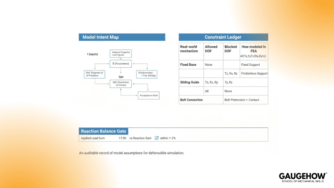
Real-World Mechanism | Allowed Motion (DoF) | Blocked Motion (DoF) |
Bolt + clamp | Slip may be limited by friction | Separation in clamp direction (up to contact rules) |
Pin joint | Rotation about the pin axis | Translation normal to the pin axis (at bearing surface) |
Weld | Minimal relative motion | Translations and rotations across the weld line |
Bearing seat | Tangential slip may exist | Normal penetration (contact) |
Two failure modes show up fast:
Over-constraint makes the model too stiff and inflates stress near supports while suppressing deflection.
Under-constraint leaves rigid body motion and produces singular behavior or meaningless displacements.
Sanity check: for clean linear statics, net reactions typically match applied loads within about 1% to 2% when the load path is consistent.
If you see “fixed-edge stress spikes,” it is often a boundary condition artifact. Using more realistic compliance or elastic supports can reduce false singular behavior at constraint edges. (engineering.com)
Meshing And Convergence
Meshing is how the continuous domain becomes a solvable discrete problem. Convergence tests whether your result is stable as the discretization changes.
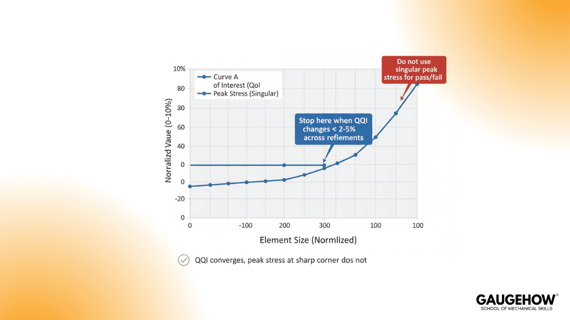
Mesh Convergence, Done Like An Engineer:
Pick one QoI such as deflection at a functional point, average stress over a section, or reaction load at a mount. Refine the mesh and track that QoI until additional refinement changes it negligibly.
One rule you should treat as non-negotiable:
Peak stress at a true stress singularity rises with refinement, so converge displacement and nearby stresses instead of chasing the hotspot. (Innovation Space)
That does not mean the model is useless. Singularities are local. Displacements and stresses away from the singular feature can still be correct enough for decisions.
Sanity check: If your decision flips only because you changed the element size at a sharp corner, you are using the wrong metric.
Post-Processing And Reporting
Post-processing is interpretation under assumptions, not visualization. You should explicitly state which variables were solved directly, which were derived, which constitutive assumptions were used, and how outputs map to the design decision.
A clean reporting habit is to separate:
Solved field: displacement (\mathbf{u}) (and temperature, if coupled).
Derived outputs: stress, strain, factor of safety, contact pressure, using the constitutive model you assumed.
Decision statement: limit value, computed value, and margin in consistent SI units.
Model Quality Gates
Confirm constrained DoF match the Constraint Ledger; you are solving the wrong mechanism.
Verify the reaction balance closes; otherwise, the load path is broken.
Check contact status and sliding or separation against the real interface behavior.
Converge the QoI, not peak stress at geometric sharpness.
State solved versus derived outputs, so reviewers can trace assumptions.
Record units, sign conventions, and coordinate frames, so results are repeatable.
Model Acceptance Criteria Table
Check | Why It Matters | Acceptance Target | Evidence To Save |
Intent lock | Prevents wrong objective | Reviewer restates purpose in 20 seconds | One-page intent map |
Constraint ledger match | Prevents false stiffness | No habit-based “fixed support.” | Constraint ledger + screenshots |
Reaction balance | Catches broken load paths | Within ~1% to 2% for clean linear statics | Reaction report |
Mesh convergence on QoI | Makes the result stable | The last two refinements change QoI from < 2% to 5% | Convergence plot/table |
Singularity handling | Prevents hotspot chasing | Peak singular stresses are not used for pass or fail | Note + location rule |
Traceability of derived outputs | Makes stress meaningful | The constitutive assumption is stated and consistent | Material card + assumption note |
Decision with margin | Forces engineering closure | Limit, actual, and margin in SI units | Decision table |
Common Mechanical Failure Modes
Over-constrained supports that block the DoF the hardware allows, causing false stiffness and inflated support stress.
Under-constrained models with rigid body motion produce singular solutions or meaningless displacements.
Point loads or point constraints create artificial stress singularities near the application region.
Contact definitions that silently open or over-stick, shifting stiffness first and stress second.
Converging peak stress at a sharp corner instead of converging the QoI that drives the decision.
Reporting derived stress without stating material law and assumptions, making the number un-auditable.
How To Implement
Write the Model Intent Map, then build the Constraint Ledger.
Solve the simplest credible model first, then add complexity one assumption at a time.
Converge the QoI, document quality gates, and report with a margin.
Conclusion
FEA modeling is the controlled conversion of a real problem into a finite, solvable system. In practice, the highest-leverage improvements are intent locking, realistic boundary conditions, auditable constraints, and mesh convergence on the QoI that actually drives the decision. When those are in place, FEA becomes a reliable design analysis method rather than an expensive visualization step.
FAQ
What Is FEA Modeling?
It is converting a continuous engineering problem into a finite element model with explicit DoF, boundary conditions, and loads, so primary unknowns can be solved and dependent outputs derived.
Why Do Stresses Sometimes Increase With Mesh Convergence Refinement?
If peak stress climbs with refinement, assume a singularity at a sharp corner or constraint; report hotspot over a probe radius, not node max.What Is The Fastest Credibility Check For A Static Model?
Reaction balance. If reactions do not match applied loads, the load path or constraints are inconsistent.
Where Do Most FEA Errors Start?
In pre-processing, geometry cleanup, meshing, and boundary conditions encode the assumptions that dominate results. (Siemens Digital Industries Software)
Why Should Modeling Discipline Happen Early In Design?
Lock modeling discipline before freeze, because early choices lock most lifecycle cost; track ECO churn rate as the control metric.
References
NASA, “Cost Effectiveness Considerations” (15% spent, ~75% committed). (NASA)
Siemens Digital Industries Software, “Finite element pre- and post-processing” (pre-processing is often the longest step). (Siemens Digital Industries Software)
ANSYS, “What is Finite Element Analysis (FEA)?” (definition and framing). (Ansys)
NAFEMS, “Management of Finite Element Analysis” (quality management framing). (NAFEMS)
Engineering.com, avoiding singularities driven by boundary condition choices. (engineering.com)
CAD-CAM-CAE Work Platform
Find or Post CAD, CAM and CAE freelance projects, full-time jobs and Internships.
GaugeHow is the platform built for core engineering work. Whether you need a freelancer for a CAD project, a full-time hire, or an engineering intern,post it here and get matched with the right person.
Our Courses
Complete Course Library
Access to 40+ courses covering various fields like Design, Simulation, Quality, Manufacturing, Robotics, and more.


