Finite Element Analysis (FEA): Types, Uses, Software


Deepak S Choudhary
Finite Element Analysis helps you predict stress, temperature, vibration, and failure before you cut metal. This guide stays focused on three things searchers want: the main FEA types, real FEA applications, and how to pick FEA software that matches your physics, accuracy needs, and budget.
What Is Finite Element Analysis
Use FEA for sign-off decisions: you take a real part, idealize it, solve it using FEM, then interpret outputs like stress, strain, temperature, deflection, or frequency to judge margin. FEM is the numerical machinery; FEA is the applied workflow, including assumptions, boundary setup, and pass-fail checks, and documented assumptions others can audit.
You discretize the geometry into elements, assign material models, apply loads and constraints, solve, then sanity-check reactions before reading peaks.
In plain terms, it is computer-based analysis that predicts response from loads and boundary conditions, which is what most first-time FEA buyers are actually asking.
Accuracy often moves fastest with element order. Quadratic tets are typically 10-node solids, while higher-order bricks can be 20-node, and that changes curvature capture and hotspot stress. Prove it with one refinement run at the critical feature.
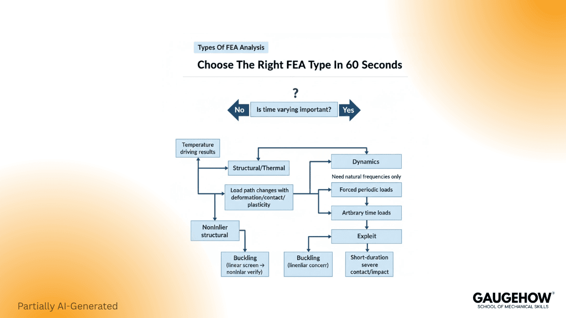
Types Of FEA Analysis
Most engineers lose time by picking the wrong physics first. The fastest way to choose is to start from the question you must answer, then match it to the analysis family.
Your question | Best starting point | What to verify first |
“Will it yield under load?” | Linear static structural | Load path, constraints, and reaction balance (NAFEMS) |
“Will it buckle?” | Linear buckling, then nonlinear if needed | Imperfections and boundary realism |
“How does it vibrate?” | Modal, then harmonic or random response | Modal trust hinges on realistic supports, correct mass distribution, and physically sensible mode shapes. |
“Does it survive impact or crash?” | Explicit dynamics | Explicit stability hinges on the critical time step and clean contact definitions. |
“Will it overheat?” | Steady or transient thermal | Heat loads, convection assumptions |
“Will it crack or fail progressively?” | Nonlinear, fracture, or damage models | Material model validity and mesh objectivity |
If you are searching for types of FEA analysis, here is the clean map that covers almost all industrial work:
1) Linear Static Structural
Use it when materials stay elastic, and deformations are small. This is the first pass for brackets, housings, frames, and bolted joints when you are still shaping the design.
2) Nonlinear Structural
Choose this when you have large deformation, plasticity, rubber, contact, or any load path that changes while loading. This is where convergence controls and realistic contacts decide success.
3) Dynamics
Modal gives natural frequencies and mode shapes. Harmonic and transient dynamics predict response undertime-varyingg loads. Modal analysis is explicitly about natural frequencies and mode shapes, and FEM is a standard way to compute them. (Wikipedia)
4) Buckling
Linear buckling is a screening tool. Nonlinear buckling is what you use for design decisions once imperfections and post-buckling matter.
5) Thermal and Thermo-Mechanical
Thermal alone predicts temperature fields. Thermo-mechanical couples those temperatures into stress and distortion.
6) Explicit vs Implicit Time Integration
Choose explicit for impacts and other fast, strongly nonlinear events because it advances without equilibrium iterations each increment, but the critical time step is tiny, and the runtime can explode. Monitor time step size and contact energy.
Use implicit for slow loading and long transients because it can take larger steps while enforcing equilibrium through iterations, so the cost scales with convergence rather than time step count. Track iteration count and cutbacks.
FEA Applications
FEA applications are easiest to understand when you tie each industry use case to the failure mode being prevented.
Automotive
Crashworthiness, durability, and noise vibration harshness work lives here. Explicit dynamics dominate crash, while modal and fatigue-driven stress are common for durability. (saemobilus.sae.org)
Aerospace
Stiffness, buckling margins, and weight dominate. Shell modeling, buckling, and nonlinear verification are daily tasks.
Civil And Infrastructure
Concrete cracking, rebar interaction, foundation settlement, and seismic response push you into nonlinear material behavior and dynamics.
Electronics And Consumer
Drop tests, thermal hot spots, and creep in plastics are common. Transient thermal plus nonlinear contact often shows the real risk.
Energy And Pressure Equipment
Thermal gradients, bolt preload, gasket sealing, and fatigue near discontinuities are typical.
Here is the rule that keeps FEA applications honest: match the analysis to the decision. If you only need a stiffness comparison, do not start with a fracture model. If you must sign off on safety, do not stop at a single mesh.
FEA Software
FEA software selection should be driven by physics, contact complexity, solver scale, and the ecosystem you need around it.
A practical shortlist by fit
General purpose, broad capability
Reach for ANSYS Mechanical when you need a fast, general structural solver that covers linear to nonlinear plus coupled load cases.
Use Abaqus when contact and material nonlinearity dominate, and large assemblies demand tight step control.
Cloud and collaboration-focused
Pick SimScale for browser-first FEA with simple sharing links and review loops; it teaches concepts through guided workflows, keeping distributed teams aligned quickly.
Open source and research-friendly
Choose CalculiX when the budget is zero, and you want FEM solving, you can audit, script, and reproduce across many machines reliably.
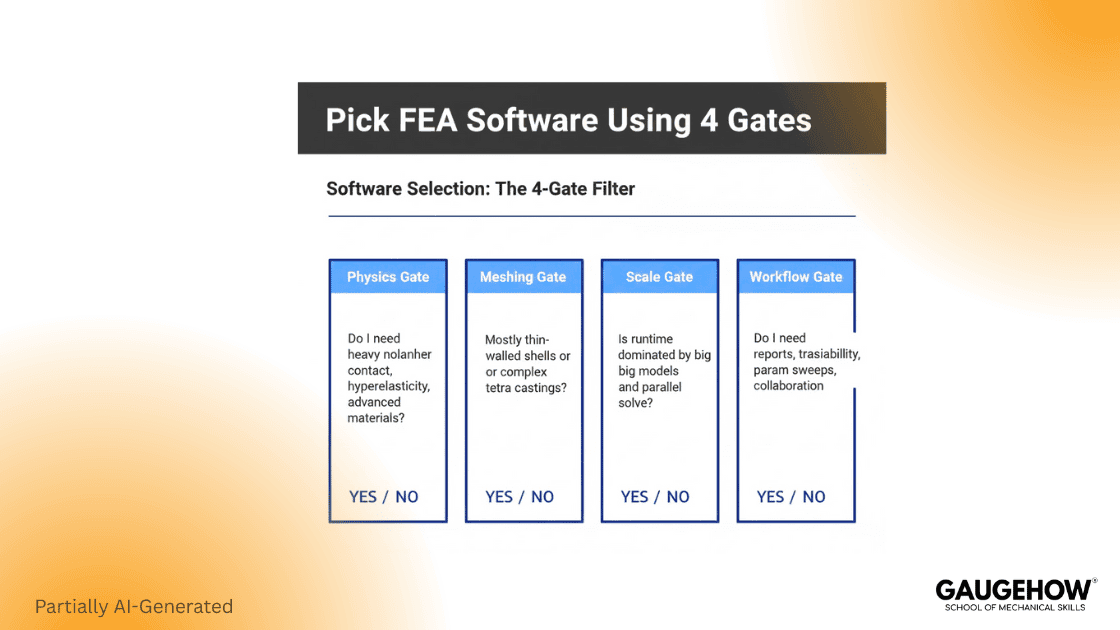
How to choose without bias
Pick your FEA software using four gates:
Physics gate
If you need heavy nonlinear contact, hyperelasticity, or complex material behavior, prioritize solver robustness and contact controls.
Geometry and meshing gate
If most of your models are thin-walled, shell workflows, and midsurface tools matter more than brute mesh size. If you mesh complex castings, tetra quality controls matter.Speed and scale gate
If runtime dominates, you need parallel performance and good preconditioners, plus the right element order for the job. (help.altair.com)Workflow gate
Ask what you will actually do weekly: automated reports, parametric sweeps, design studies, or traceable sign-off packs.
A Workflow You Can Trust
Start with geometry cleanup and correct units. Move to materials that match the expected strain range. Apply loads through realistic interfaces, not point forces. Mesh with intent, then solve, then validate the story.
The minimum credibility loop
Check reactions and balance.
If the total reaction does not matchthe applied load, the model is not describing equilibrium in the way you think it is. NAFEMS guidance exists because this input quality step is where most bad answers start. (NAFEMS)
Run a convergence trend, not a single mesh.
Use at least two mesh levels and compare the decision quantity. For stress hot spots, track trends and avoid judging at a singularity.
Prove boundary conditions
The most common failure mode is over-constraint, which artificially stiffens the model. A quick way to catch it is to compare the deformation shape to what the hardware can physically do.
How We Think Differently
Good FEA is not “results first.” It is “decision first.” Define what you must decide, then choose the simplest analysis that can answer it with defendable assumptions. That mindset aligns with how simulation credibility is treated in verification and validation standards, where the goal is a shared framework and language for model credibility. (ASME)
Evidence Pack Checklist
Use this when a reviewer asks, “Why should I trust this model?”
Model objective and acceptance criteria
Loads and constraints justification with screenshots
Mesh settings and convergence trend for the decision quantity
Material source and assumptions
Reactions and balance summary
Result plots tied to the decision, not just contour art
This is the difference between a pretty image and an engineering answer.
FAQ
1) What is the difference between FEM and FEA?
FEM is a mathematical method. FEA is the engineering process of applying FEM to a real part, solving it, and interpreting the results for design decisions. (Ansys)
2) Which FEA type should I start with for a new part?
Start with linear static if you expect small elastic behavior. Move to nonlinear when contact, plasticity, or large deformation changes the load path.
3) Why do two meshes give different stress results?
Meshes disagree because element type, order, and sizing control stress-gradient resolution at notches. Quadratic solids, like 10-node tets, follow curvature better, shifting peaks.
4) When should I use explicit dynamic
Use explicit for impacts and other short, severe nonlinear events where contact drives behavior, and the stable time step sets the runtime. Confirm duration fits your time window.
5) What should I look for when choosing FEA software?
Match the physics capability, meshing workflow, solver scale, and reporting needs to your recurring jobs, not to a feature list.
References
ASME, Standard and guidance pages for verification and validation in computational solid mechanics (ASME)
MIT OpenCourseWare, “Finite Element Analysis of Solids and Fluids I (2.092)” (MIT OpenCourseWare)
Altair Help (Radioss theory), solid element references for 10-node tetra and 20-node brick element families (help.altair.com)
CAD-CAM-CAE Work Platform
Find or Post CAD, CAM and CAE freelance projects, full-time jobs and Internships.
GaugeHow is the platform built for core engineering work. Whether you need a freelancer for a CAD project, a full-time hire, or an engineering intern,post it here and get matched with the right person.
Our Courses
Complete Course Library
Access to 40+ courses covering various fields like Design, Simulation, Quality, Manufacturing, Robotics, and more.


