Linear vs Nonlinear FEA: Stress-Strain Curve Guide


Deepak S Choudhary
Linear and nonlinear choices in FEA are decisions about assumptions and data, not settings. Linear holds while stiffness stays proportional, and constraints do not switch state. Once yielding, large deflection, or contact changes the load path, you neea d nonlinear model. This guide gives solver-ready inputs and review-grade checks.
Difference In FEA
Linear analysis assumes constant stiffness, so results scale proportionally with load.
Nonlinear analysis updates stiffness during the step, so load history and state changes matter.
Go nonlinear once plasticity, path-dependent deflection, or contact open-close behavior is expected to avoid false margins.
What actually makes it nonlinear
Driver | What changes | What linear gets wrong |
Material | Stress-strain slope changes after yield | Overpredicts stress, misses redistribution (WUSTL Engineering Classes) |
Geometry | Stiffness changes with deflection | Misses membrane action, post buckling paths (ansyshelp.ansys.com) |
Contact | Invent | - |
Linear Analysis Validity
For quick stiffness and load-path triage, linear runs are the fastest lever in early reviews. The trap is that results can look smooth even after you pass the proportional limit, so check peak stress versus yield as a sanity metric before you freeze the design.
Approve a linear model only if three conditions stay stable through the load step: the material never leaves elasticity, deformation is small enough that geometry does not redirect forces, and supports or contacts never switch from fixed to free. If any breaks, use linear for debugging and mesh checks, then move to nonlinear for decisions.
Nonlinear Setup Controls
Nonlinear runs fail less from “hard math” and more from unmanaged transitions. Your job is to control when the model changes stiffness, and to help the solver follow that path without taking steps that are too large.
The controls that matter most
Automatic stepping is your first lever when nonlinear convergence degrades, because the solver can cut the increment, roll back, and retry with a smaller step after a failed attempt. That step-halving recovery is the core robustness mechanism, so log minimum substep size and how often cutbacks occur.
Line search helps when the Newton correction jumps past the solution, which shows up often with contact and plasticity. Stabilization can damp local oscillations and contact chatter, but you must verify that the added energy stays a small fraction of strain energy. Use arc length when the response follows an unstable path, such as snap-through, because simple load control will stall.
Common divergence patterns
What you see | Likely cause | Fix that usually works |
Diverges at the first increment | Missing constraints or rigid modes | Add minimal constraints and verify reactions |
Contact iterations explode | Penalty stiffness is too high or bad pairing | Soften contact penalty, tighten contact resolution, and validate normals and contact pairs. |
Plasticity fails immediately | Curve units wrong or wrong strain type | Re-enter the material curve, then verify units and whether stress-strain is true or engineering. |
Converges then collapses | Snap through or unstable path | Switch to arc-length control and add small imperfections when instability or snap-through is present. |
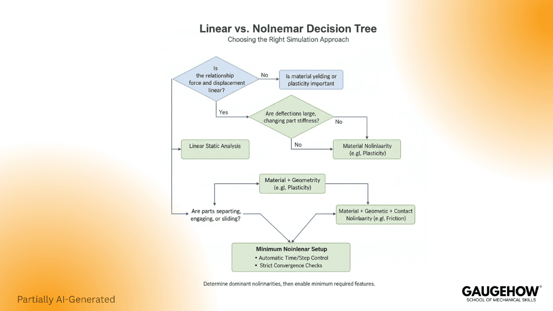
The decision flow you can defend in review
If yielding is plausible anywhere, plan nonlinear with a solver-ready curve. If the contact status can change, plan nonlinear contact. If deflection can change the load path, enable geometric nonlinearity. This is the same practical framing you see repeated in strong engineering explainers and vendor guidance, because it matches real failure modes. (Control.com)
Stress Strain Curve Data Pack For Solvers
Most competitors explain the curve. To win trust, you need an input artifact that engineers can copy into a workflow.
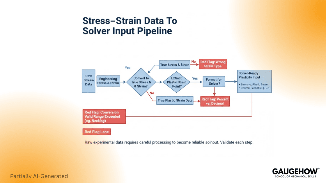
Engineering to true conversion
True strain and true stress are commonly derived from engineering measures using:
ε_true = ln(1 + ε_eng)
σ_true = σ_eng (1 + ε_eng) (Innovation Space)
Bold warning: Only convert engineering to true up to uniform elongation, meaning before necking starts. After necking, the strain localizes in the gauge, so a simple conversion does not represent the actual material curve. Track elongation at UTS as the cutoff.
If post-UTS behavior affects your result, do not treat a converted tensile curve as ground truth. Use a method built for the necked regime. Bulge testing is one accepted route to extract flow data beyond uniform elongation.
Abaqus plasticity input rule
Start the plastic table with yield stress at zero plastic strain, or you corrupt the onset behavior and convergence.
Beyond yield, input the curve as true stress paired with logarithmic plastic strain; keep the yield entry at log plastic strain zero. Then check units and slope, or you will see hardening spikes and failed steps.
Example input table
This is a format example only, not material data. Units and strain definition must match your solver settings and your test basis.
True Stress (MPa) | Plastic Strain (log) |
400 | 0.000 |
420 | 0.010 |
445 | 0.025 |
465 | 0.040 |
480 | 0.055 |
Row 1 is yielded with plastic strain set to zero. That is the rule. (WUSTL Engineering Classes)
Units trap
Most solver failures I review trace back to one of these:
Stress is entered in MPa while the model is in Pa, so the material becomes 10⁶ times softer or stronger than intended.
Strain entered as a percent instead of a decimal, so plastic strain is off by 100.
Engineering strain is fed where log plastic strain is expected, especially in Abaqus-style plasticity tables. (blog.technia.com)
What to request from the test lab
Ask for raw force extension, specimen geometry, gauge length, strain measurement method, yield definition used, and the uniform elongation point. If you expect to use the curve past uniform elongation, state that early and request an appropriate characterization approach, such as bulge testing, rather than forcing a conversion beyond necking. (AHSS Guidelines)
Micro Case Studies
Bracket with a clearance gap
Linear treats the joint as closed from step one, so load sharing looks smooth. Nonlinear lets the gap close later, stiffness rises abruptly, and hot spots move into the bearing patch. Track contact status.
Thin plate where deflection changes the load path
Linear stays in pure bending. Nonlinear captures membrane tension once it sags, raising stiffness and shifting peaks. Watch midspan deflection.
Yielding near a notch
Linear keeps amplifying notch stress with load. Nonlinear yields locally, stress redistributes, and plastic strain becomes the driver. Monitor PEEQ at the hotspot.
FAQ
When is linear analysis acceptable in FEA
Use linear only when the response stays elastic, contacts and constraints keep the same state, and deflection is small enough that the load path does not shift. If not, linear is just a baseline for setup checks.
Difference between linear and non-linear analysis in fea
Linear assumes fixed stiffness, so doubling the load doubles stress and deflection. Nonlinear updates stiffness as it steps through yielding, geometry change, and contact, so simple scaling no longer applies.
What is the first plasticity data pair in Abaqus?
The first plasticity row is the yield stress at zero plastic strain. It marks where plastic flow begins and sets the reference for the curve.
Why does non-linear analysis fail to converge
Nonlinear fails when the model is under-constrained, contact is too stiff, the step size is too coarse, or the material data is inconsistent in units or strain definition. Reduce increment, let auto-stepping work, read diagnostics, and use arc length if snap through appears.
When do I need a true stress-strain curve?
You need true stress-strain when plasticity or large strain kinematics matter in the model. Engineering to true conversion is only valid up to uniform elongation. After necking, the simple conversion breaks, so use a post-necking method if that range drives decisions.
References
WUSTL Abaqus docs, the first data pair yields with plastic strain zero. (WUSTL Engineering Classes)
TECHNIA, Abaqus plasticity input uses true stress and logarithmic plastic strain. (blog.technia.com)
ANSYS Innovation Space PDF, conversion valid only up to necking; beyond necking, not meaningful. (Innovation Space)
AHSS Guidelines, true stress strain is valid only through uniform elongation and bulge testing beyond. (AHSS Guidelines)
ANSYS Help, nonlinear diagnostics including automatic time stepping, line search, stabilization, arc length. (ansyshelp.ansys.com)
CAD-CAM-CAE Work Platform
Find or Post CAD, CAM and CAE freelance projects, full-time jobs and Internships.
GaugeHow is the platform built for core engineering work. Whether you need a freelancer for a CAD project, a full-time hire, or an engineering intern,post it here and get matched with the right person.
Our Courses
Complete Course Library
Access to 40+ courses covering various fields like Design, Simulation, Quality, Manufacturing, Robotics, and more.


