Finite Element Analysis Guide: Steps + Examples


Deepak S Choudhary
Finite element analysis is a simulation workflow to predict how a part behaves under real operating conditions. It uses the finite element method to approximate stresses, deflections, temperatures, and dynamic response from your loads, materials, and constraints.
You will learn a setup workflow, a review-ready proof block, and a clean way to pick tools. It is for engineers and students who need defensible results.
You can run a simulation and still doubt it. That doubt is healthy. Most wrong results look clean. They fail because loads are guessed, constraints are convenient, and contacts are skipped.
So we will keep this simple and strict. You will learn the workflow, then the checks. You will also know where time goes, because model preparation often dominates the schedule.
By the end, you will know what to trust and what to question.
What Is Finite Element Analysis
Finite element analysis is an engineering workflow for predicting part behavior.
It uses the finite element method on a meshed model, then turns the results into a design decision.
Most teams use it when the shape, loading, or material behavior makes hand solutions unrealistic. Accuracy depends less on the solver and more on what you told it.
The solver cannot guess the real world. It will only follow your loads, constraints, contacts, and material data.
Credibility comes from evidence, not plots. Verification proves the math and numerics are behaving, and validation proves the model matches the physical response.
FEM vs FEA
FEM is the mathematical technique that discretizes the domain. FEA is the applied workflow around that technique, including setup and interpretation. (Ansys FEM vs FEA distinction - Ansys)
That split keeps you honest because most errors start before solving.
When It Fits
Use it when load paths are complex, or when shapes are not simple. Use it when contacts and stiffness changes matter. But avoid it when inputs are unknown, because unknown inputs create confident noise.
A quick hand check still belongs in your process. It anchors the scale.
How The Fea Method Works
FEA runs on a repeatable setup loop. Idealize the part, mesh it, assign material behavior, apply loads and constraints, solve, then interpret with basic credibility checks.
Software UIs change, but the underlying method does not.
Most time is spent before solving on geometry cleanup, meshing, and boundary definition. Speed comes from disciplined assumptions and reusable templates.
Build A Fea Model That Does Not Lie.
A fea model should start with one decision. Ask what you must decide today, and what metric drives it. Then you model only what changes that metric.
Geometry And Element Choice
Simplify geometry with intent. Remove cosmetic details, but keep features that steer stiffness. Use shells for thin plates, use solids for thick parts, and use beams only when the structure is truly slender.
Materials must match your load range. Linear elastic is fine for small strains, but yielding needs plasticity, or your stiffness becomes fiction.
Loads, Constraints, And The Hidden Risk
Loads must follow the real load path. Constraints must represent how the part is held. If you “lock” faces that can move in reality, stresses will spike in fake ways. (NAFEMS practical advice on loads and boundary conditions - NAFEMS)
Units deserve paranoia. A millimeter model with a meter load can look believable, and still be wrong.
The Credibility Loop You Should Run First
Before you refine anything, run this loop:
Check total reactions match applied loads.
Check that the deformation shape matches intuition.
Check hot spots align with load transfer.
Refine only where gradients are physical.
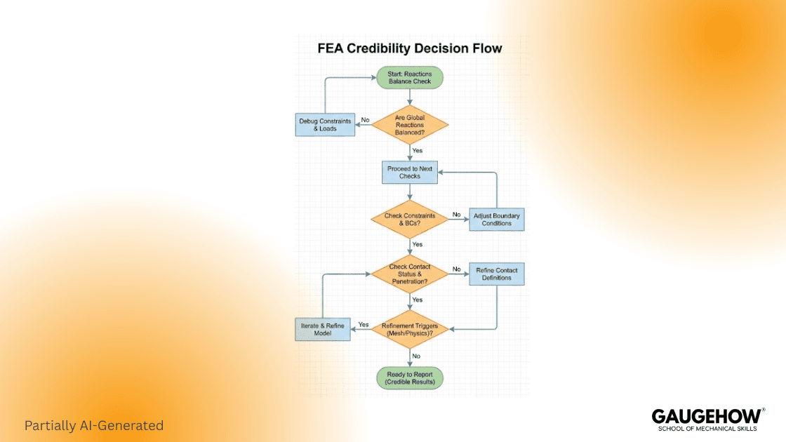
This takes minutes, and it saves weeks.
Common Mistakes (And How To Avoid Them)
Over-constraining the face so the part cannot breathe. Fix it by using minimum constraints and symmetry only when valid. (NAFEMS boundary condition guidance - NAFEMS)
Applying forces where loads are not transmitted. Fix it by modeling the interface or using distributed loads.
Trusting peak stresses at sharp corners. Fix it by reporting a path or area metric away from the corner.
Refining the whole mesh blindly. Fix it by refining only where gradients live. (Abaqus mesh refinement intent - classes.engineering.wustl.edu)
Ignoring solver warnings because contours look smooth. Fix it by treating warnings as physics questions first.
Skipping a balance check. Fix it by comparing reaction totals to applied loads every run.
Mesh And Convergence With A Review Ready Proof Block
Mesh is where accuracy is earned, and also where time disappears. You need a plan. You refine in controlled steps, and you watch decision metrics stabilize. (Abaqus mesh convergence - classes.engineering.wustl.edu)
A Review Ready mesh convergence study Proof
Mesh convergence: solve the same case on coarse, medium, and then fine mesh and compare one chosen output. Accept it when the output shift is within your tolerance.
Boundary condition: constrain motion only at the fastener bearing patches because the support is carried through the bolted interface into the backing structure. Avoid locking a whole face just to make the model behave.
Micro case with numbers
Steel L bracket, 6 mm thick. Apply 1000 N downward on the free end. Use E = 200 GPa and nu = 0.3.
Mesh level | Element size (mm) | Max displacement (mm) | Reaction sum (N) | Stress metric (MPa) |
Coarse | 5.0 | 0.42 | 998 | 165 |
Medium | 3.0 | 0.35 | 1001 | 182 |
Fine | 2.0 | 0.33 | 1000 | 186 |
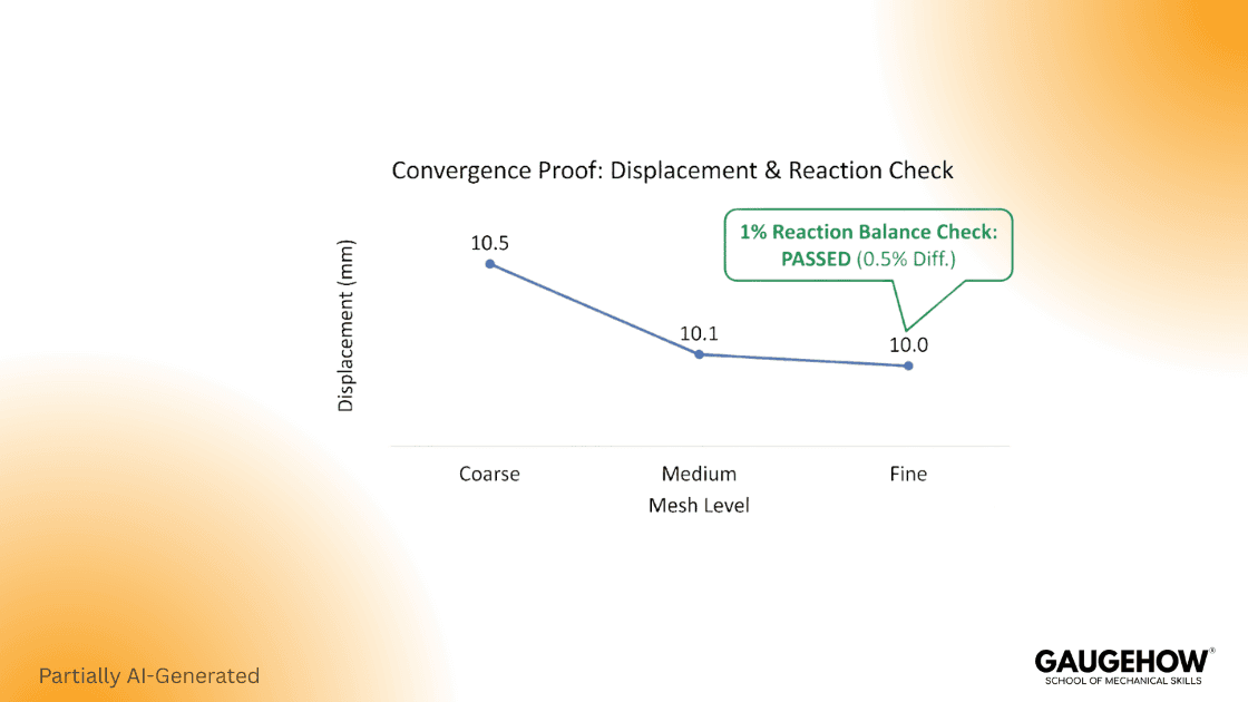
Explicit review check
Reaction sum is within 1 percent of the applied 1000 N load, so global equilibrium is behaving as expected.
Results for the Structural Analysis, Finite Element Method Work
Most day-to-day work is structural, so it helps to think in structural analysis finite element method terms. You are checking stiffness, stress, and stability under loads, and you are doing it with controlled assumptions.
Linear Static Versus Nonlinear
Linear static is a good first pass. It is stable and fast. But contact changes stiffness, and large deflections change load paths, and plasticity changes stiffness too. When those effects matter, you move to non-linear. (Credibility framing - ASME)
Stress Reporting That Does Not Mislead
Stress plots are useful, but only with context. Peaks at constraints and sharp corners often reflect modeling artifacts. So report a metric away from the sharpest edge, and always pair stress with displacement trends.
Choosing finite element analysis software Without Guesswork
Finite element analysis software is not just a solver. It includes pre-processing for geometry and meshing, and it includes post-processing for reporting. (Siemens pre- and post-processing framing - Siemens Digital Industries Software)
Choose By Physics First
Start with your dominant physics. Linear structure is common. Contact-heavy problems need robust nonlinear behavior. Dynamics and thermal problems also shift the tool needs.
Choose By Workflow And Review Culture
If you need repeatability, scripting matters. If you need traceability, reporting matters. If you need team trust, training, and templates matter.
A tool that nobody can explain will not help you.
Frequently Asked Questions
What Is The Difference Between FEM And FEA?
FEM is the math method: it turns a continuous body into elements and assembles the governing equations.
FEA is the engineering workflow: you set up loads and constraints, run the solve, check sanity, and turn plots into design decisions.
How Do You Explain Finite Element Analysis Simply?
Finite element analysis is a way to predict how a part behaves by splitting it into small pieces, solving the physics on those pieces, then reading the results against a requirement like strength, stiffness, fatigue life, or temperature limit.
What Makes a FEA Model Trustworthy?
A model is trustworthy when: the load path is believable, reactions and moments balance, constraints do not fake stiffness, and the result you care about stays stable when you refine the mesh or adjust modeling choices. If small setup changes swing the decision, the model is not ready.
Do I Always Need a Mesh Convergence Study?
Not always a long one, but you do need a convergence habit. Run at least two meshes and track one decision metric like peak stress away from singularities, displacement at a critical point, or strain energy. Stop when the metric change is small enough that it would not change your go or no-go decision.
How Should I Choose Finite Element Analysis Software?
Pick software by physics coverage first, then solver robustness for your problem type, then workflow fit: CAD cleanup, meshing control, contacts, materials, automation, and reporting. Also, check licensing and support reality, because the best solver is useless if your team cannot run it when deadlines hit.
References
Abaqus documentation, “Mesh convergence” (Convergence basics). (classes.engineering.wustl.edu)
ASME, “Standard for Verification and Validation in Computational Solid Mechanics” (Credibility framing). (ASME)
Autodesk Support, “How to Perform a Mesh Convergence Study” (Practical convergence workflow). (Autodesk)
NAFEMS, “Practical Advice” webinar material (Loads and boundary condition realism). (NAFEMS)
Conclusion
A strong analysis is not a pretty contour. It is clear assumptions and stable metrics. Start with a small scope, keep the load path honest, and refine with purpose. When you can show balance and convergence, your results become easier to trust and easier to defend.
CAD-CAM-CAE Work Platform
Find or Post CAD, CAM and CAE freelance projects, full-time jobs and Internships.
GaugeHow is the platform built for core engineering work. Whether you need a freelancer for a CAD project, a full-time hire, or an engineering intern,post it here and get matched with the right person.
Our Courses
Complete Course Library
Access to 40+ courses covering various fields like Design, Simulation, Quality, Manufacturing, Robotics, and more.


