
20 Technical CMM Interview Questions
Learn More in This Video
Subscribe to GaugeHow for More
Imagine this for a second.
You hire a "Senior" CMM Programmer on Monday.
Their resume looks perfect. They list PC-DMIS, Calypso, and 10 years of experience. They passed the HR screen easily.
Two weeks later, reality hits.
They crash a $5,000 probe head into a clamp. Or worse, they pass a pallet of bad parts because they don't understand basic alignment physics.
In that moment, you realize something uncomfortable:
Keywords on a resume are not the same as competence.
Most "senior" applicants are actually just experienced operators. They can push buttons, but they cannot troubleshoot geometry.
That is exactly why your interview process needs to change. You cannot rely on generic questions. You need to audit their math, their logic, and their panic response.
Below is a practical guide to the 20 technical CMM interview questions that actually matter. These questions separate the button-pushers from the true metrologists.
Difficulty Signal: Senior Level Only
Disclaimer: These are senior-level questions. They require deep knowledge of vectors, GD&T standards, and error theory. If a candidate answers all twenty confidently, hire them immediately.
Part 1: Alignment Logic (The Knowledge Filter)
The alignment is the foundation of every measurement. If the alignment is wrong, every subsequent number is a lie. A fake programmer hides here. A real one knows the math.
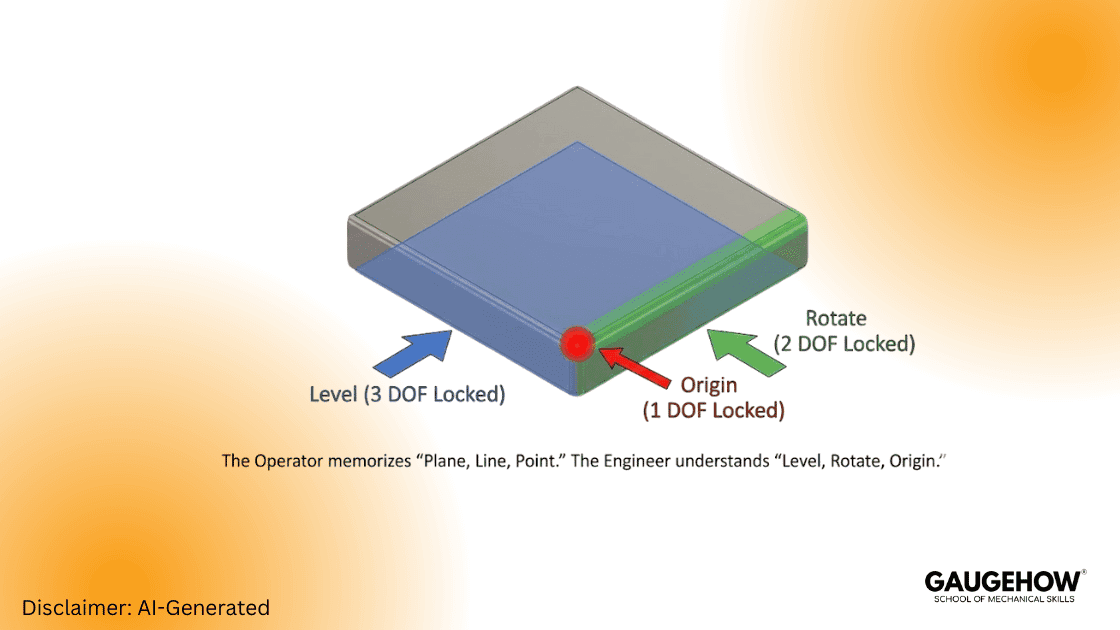
1. Explain the 3-2-1 alignment rule to me.
Answer:
Most candidates give the textbook definition: "It uses a plane, line, and point." That is the operator's answer.
The engineer's answer focuses on degrees of freedom (DOF). They must explain exactly which spatial degrees are locked by each feature.
Plane: Leveling (3 DOF Locked: 1 Translation, 2 Rotations)
Line: Rotation (2 DOF Locked: 1 Translation, 1 Rotation)
Point: Origin (1 DOF Locked: 1 Translation)
If they cannot list the specific degrees of freedom, they don't understand the machine. They are just memorizing steps.
2. When do you need an Iterative Alignment?
Answer:
You use this for parts lacking distinct, flat datums. Think of complex surfaces like car body panels, turbine blades, or molded plastics.
Standard 3-2-1 logic fails here because the datums are often target points on a curved surface. The CMM must "best fit" the physical points to the CAD model. It measures, shifts the grid, and loops until the error drops below a set threshold.
3. What is the difference between a "Machine Alignment" and a "Part Alignment"?
Answer:
The machine alignment is the CMM’s native coordinate system (Home position). The part alignment moves that grid to the workpiece itself.
Novices often program based on machine coordinates. This is dangerous. If you move the fixture two inches, the program crashes. A pro always transforms the alignment to the part immediately.
4. How does Form Error affect your alignment?
Answer:
Imagine your primary datum plane has a 0.05mm bow in it. If you level to the high points, your entire coordinate system tilts.
This tilt acts like a lever. The further you measure from the origin, the more massive the error becomes. A skilled CMM programmer counters this by using "Least Squares" algorithms to average the error, rather than relying on unstable high points.
5. Why would you level to a cylinder instead of a plane?
Answer:
You do this when the functional axis of the part is a bore or shaft, not a face. Think of a transmission case or hydraulic manifold.
If the face is not perfectly perpendicular to the bore, leveling to the face creates cosine error. You must align to the feature that actually mates in assembly.
Part 2: GD&T "Hard Mode" (Interpretation)
GD&T is the language of the print. GD&T interview questions reveal if a candidate can read that language or if they just guess.
6. Explain True Position with an MMC modifier.
Question: I have a 10mm hole. The tolerance is 0.5mm at MMC.
Assume the limits of size are 10.0mm – 10.3mm.
The hole measures 10.2mm. What is my total position tolerance?
Answer:
Candidates often fail to calculate the bonus.
MMC Size: 10.0mm.
Base Tolerance: 0.5mm.
Bonus Calculation: 10.2 mm (Actual) - 10.0 mm (MMC) = 0.2 mm.
Total Tolerance: 0.7mm.
If they forget the bonus, they will scrap good parts.
7. What is the difference between Circularity and Cylindricity?
Answer:
Circularity only checks individual 2D cross-sections (slices). Cylindricity checks the entire 3D surface at once.
A part can be round at every slice but bent like a banana. Circularity passes it; cylindricity fails it. Engineers often mess this up on prints. A good programmer catches the design error before writing the code.
8. How do you inspect "Profile of a Surface" with no datums?
Answer:
This callout controls the form of the feature itself, not its location. It limits flatness, roundness, and waviness simultaneously.
You align to the feature itself (using a best-fit algorithm) and check the deviation range. The part is floating; you are only measuring its shape.
9. What is a "Simultaneous Requirement" (SIM REQ)?
Answer:
This occurs when two patterns reference the same datums with the same modifiers. The standard treats them as one giant pattern.
The part must lock into the datum structure once. You cannot shift the part to pass Pattern A, then shift it again for Pattern B. If they ask, "Can I unlock the alignment between checks?" they failed.
10. Explain "Composite Position" tolerance.
Answer:
The top frame locates the pattern to the datums (PLTZF). The bottom frame locates the holes to each other (FRTZF).
This allows a loose tolerance for the pattern's location on the part, but a tight tolerance for the holes relative to one another. It saves money on fixturing.
Part 3: Troubleshooting & Error Sources
Machines don't lie, but physics creates errors. This section separates button-pushers from metrologists.
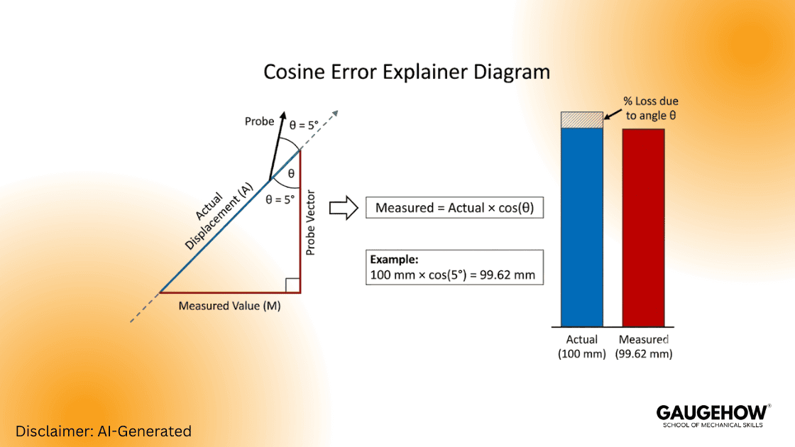
11. What is Cosine Error in a CMM measurement?
Answer:
This happens when the probe vector does not match the feature's surface normal.
If you approach a hole at a 5-degree angle, the machine compensates the ball radius in the wrong direction. This shifts the reported center of the hole. If they can't draw the vector forces, they don't understand the math.
12. Why does my pin gauge not fit, but the CMM says "Pass"?
Answer:
The CMM likely measured distinct points (e.g., 4 hits) and calculated a "Least Squares" circle. This mathematically fits a circle between the points.
However, the hole might be tri-lobed (triangular). The physical pin hits the high points of the lobes. To match the physical reality, you must scan the hole or use a "Maximum Inscribed" calculation.
13. How do you handle temperature compensation?
Answer:
Aluminum expands faster than steel. A large part measured at 30°C will fail length checks if you ignore physics.
You must enable temp comp in the software. Place magnetic sensors on both the part and the CMM scales. The software then mathematically scales the results back to the standard 20°C.
14. What is "Shanking" the probe?
Answer:
The metal shaft of the stylus hits the part instead of the ruby tip. This usually happens in deep, narrow bores.
The machine records a hit, but the data is garbage. You fix this by swapping to a larger ruby or a thinner stem (ceramic or carbide).
15. How do you validate a probe calibration?
Answer:
Don't just trust the "Calibration Complete" message. Check the Standard Deviation (StdDev). It should be near zero (e.g., < 0.005mm).
For a real test, measure a known artifact like a Ring Gage or Master Ball as a "part." If the Ring Gauge reads 0.02mm off, your CMM probe calibration is bad.
Part 4: Software & Strategy
Different software requires different mindsets. This section covers PC-DMIS interview topics and general strategy.
16. PC-DMIS vs. Calypso: What is the main workflow difference?
Answer:
PC-DMIS is procedural. It reads like code (top-down). You control every motion and logic line explicitly. It is powerful for complex scripting.
Calypso is object-oriented. You define the "Feature" and the "Characteristic," and the software calculates the path. It is generally faster for standard geometry but harder to "hack."
17. How do you optimize a program for run-time?
Answer:
Program efficiency saves money.
Minimize tool changes (they are slow).
Group features by probe angle.
Use "Fly Mode" (blended moves) around corners.
Cut out redundant clearance moves.
18. When should you use Hard Probing vs. Scanning?
Answer:
This is a trade-off between speed, accuracy, and wear.
Hard Probing: Best for 3D locations, Prismatic shapes. Downside: Misses form errors.
Scanning: Best for Form (Roundness/Flatness), Profiles. Downside: Wears tips, captures dirt/noise.
19. How do you handle a "Crash" during an interview test?
Answer:
If they crash the probe during the test, watch their reaction.
Immediate Stop: Hit the E-Stop.
Safety: Manually disengage motors.
Validation: Check the stylus for damage.
Recovery: Re-qualify (calibrate) the probe before measuring anything else.
If they try to just "keep going," fail them.
20. What is a Loop or "Do / While" command used for?
Answer:
You need loops for pallet inspections (measuring a grid of identical parts). They are also critical for iterative alignments (re-measuring until a target is hit) or writing data to external Excel files row by row.
How to Use This Guide?
For Hiring Managers:
Use this list as a live whiteboard test. Do not just ask the questions verbally. Make them draw the vector forces. Watch how they approach the problem, not just the final number.
For Candidates:
Be honest with yourself. If you cannot explain at least five of these answers, you are not ready. Study the geometry, not the definitions.
Note: Expect more GD&T to come directly from Model-Based Definition (MBD), not drawings.
Final Thoughts on the Industry
The role of a Metrologist is changing. It used to be about checking red/green lights. Now, it is about data integration and smart factories.
You need to know how the CAD affects the code. You need to know how the thermal loop affects the micron.
The questions above are the barrier to entry for the modern era. Master them.
Mechanical Engineering Courses That Industry Actually Uses
Learn Tools of Design & CAD, Analysis & Simulation, Automation & Robotics, and Industry 4.0 used in modern factories.
Join 40+ Mech Courses like GD&T, Siemens NX, SolidWorks, CATIA V5, AutoCAD, ANSYS (FEA & Fluent), ABAQUS, Creo, Fusion 360, CNC Programming, Digital Twins, Python for Mechanical, and Industry 4.0.
Our Courses
Complete Course Library
Access to 40+ courses covering various fields like Design, Simulation, Quality, Manufacturing, Robotics, and more.


