Common CMM Errors: Shop-Floor Diagnostics & Recovery Guide
Learn More in This Video
Subscribe to GaugeHow for More
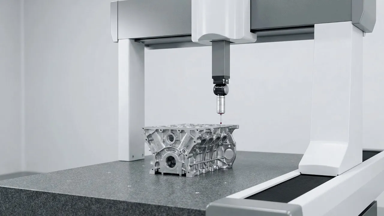
Coordinate Measuring Machines (CMMs) offer micron-level accuracy. However, that precision is useless if the system isn't under strict control. When accuracy fails, the cost isn't just a bad report. It leads to scrapped parts, wasted material, and expensive downtime.
This guide moves beyond generic advice. We look at specific CMM errors and the physics behind them. Then, we provide the actionable recovery protocols you need. We designed this for quality engineers who need to diagnose symptoms, verify calibration, and basically return to production fast.
The Field Approach: Symptom-Based Diagnostics
Technicians rarely search for "volumetric parametric errors." They search for practical problems. They ask, "Why are my holes measuring oval?" or "Why is the Z-axis drifting?"
This guide maps those physical symptoms to their technical origins. We cover mechanical wear, thermal drift, and the often-ignored mathematics of cosine error. Follow these protocols to stabilise your metrology lab.
The Nine Most Prevalent CMM Errors
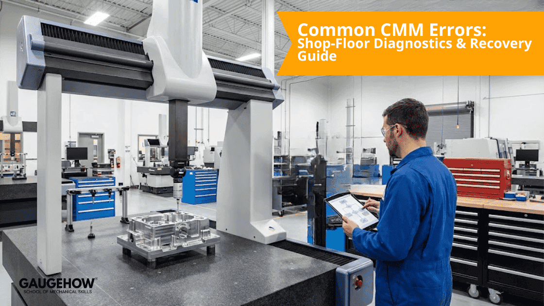
1. Volumetric Positioning Deviations
Volumetric errors are tricky. They shift feature positions across the machine's entire work envelope. You will often see that a hole diameter measures correctly, but its position relative to the datum is consistently off.
This usually happens because of underlying geometry issues. Specifically, look for axis straightness deviations, linear scale errors, or squareness drift. To fix this, stop guessing. Execute a full volumetric error map. Use certified artefacts, such as a ball bar or a step gauge. Once mapped, apply the compensation map in the controller. However, if the trend persists, replace worn styli immediately and audit the machine’s calibration history.
2. Probe Calibration Drift
Probe assembly issues are frustrating. They mimic machine failures and cause significant confusion. Typical indicators include "lobing"—where round features look like triangles—or inconsistent roundness readings.
The culprit is often simple. It could be a loose stylus, contaminated thread joints, or thermal expansion in the module. Verify probe health first. Initiate a fresh calibration routine. If the standard deviation is high, replace the stylus and clean the joints. Then, log the results.
3. Cosine Error (Angular Probe Misalignment)
Cosine error is a silent killer in metrology. It occurs when your measurement approach isn't perfectly aligned with the feature's axis. The symptom is subtle: measured lengths appear slightly smaller than reality.
Physically, this means the probe vector is not perpendicular to the surface. It isn't "normal" to the part. To correct this, force the software to align the approach vector to the surface normal. If the part geometry is complex, switch to a shorter, stiffer stylus. This minimises the mathematical impact of cosine error.
4. Fixturing Induced Distortion
A fixture has one job: restrain the part without deforming it. Does your data shift after re-clamping? Do thin-walled parts show inconsistent form? If so, the fixture is likely the problem.
This is caused by excessive clamping torque. The support points fight the part’s natural geometry, leading to elastic deformation. To fix this, adhere strictly to the 3-2-1 principle using kinematic mounts. For delicate components, switch to soft-touch fixtures. Verify the setup by measuring the part, unclamping it, and measuring it again.
5. Environmental Instability
Environmental factors are the leading source of "ghost" errors. These are readings that drift progressively through a shift.
Rapid temperature swings can affect the granite. So can floor vibration from stamping presses, or even fluctuating air lines. You must isolate the coordinate measuring machine from these vibration sources. Furthermore, monitor room temperature at the granite level, not just the wall thermostat. Generally, you need to maintain the environment within ±1 °C.
6. Software Strategy Misalignment
Software settings affect the result. You might see different fits (like Least Squares vs. Maximum Inscribed) yielding conflicting data.
The issue is often the wrong-fitting algorithm. Or, you might be using too few sample points for the feature size. To fix this, increase sampling density on form-critical features. Review your data structure as well. Avoid unjustified "best-fit" alignments that might mask actual manufacturing errors.
7. Operator Consistency Variables
If the same program yields different results with different operators, the process lacks stability.
This usually stems from inconsistent manual alignment. Or, operators might handle warm parts without thermal gloves. The solution is to lock program vectors in the code. This prevents manual overrides. Additionally, provide targeted training on vector logic and enforce strict thermal discipline.
8. Mechanical Wear and Hysteresis
Even granite-based systems age. Watch for axis-specific deviation. Also, look for poor repeatability (hysteresis) when moving back and forth to the same point.
This is basically caused by mechanical drag. Look for guideway wear, contaminated air bearings, or poor lubrication. You should trend repeatability data over time. Schedule preventive maintenance and replace worn drive components before they fail.
9. Misjudging Measurement Uncertainty
Borderline passes often turn into customer rejections. This happens because the error budget was ignored.
You must account for the combined uncertainty of the machine, the probe, and the environment. To protect yourself, calculate and publish the measurement uncertainty following ISO 17025 standards. Ensure your tolerance is at least 4x your uncertainty (maintain a 4:1 TUR).
Rapid Diagnostics: Symptom to Origin Matrix
Use this table as a quick decision map to bypass lengthy troubleshooting.
Field Observation | Probable Origin | First Diagnostic Step |
Drifting results over time | Thermal instability or Scale error | Review temp logs and air pressure stability. |
Position fails; Size passes | Cosine error or Alignment | Verify probe approach vector matches surface normal. |
Sudden "fly-away" points | Vibration or Contamination | Clean scales; inspect nearby machines for heavy impact. |
Lobe / Roundness fail | Probe Calibration | Inspect stylus ball for flats; reduce scanning speed. |
Z-axis variation | Counterbalance or Air Pressure | Check the Z-axis regulator and pneumatic cylinder balance. |
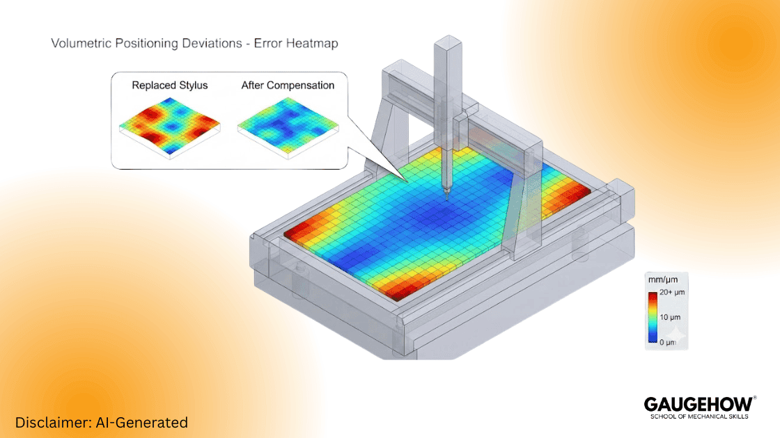
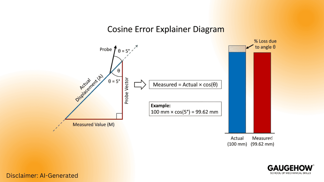
Deep Dive: The Mathematics of Cosine Error
Cosine error is mathematically simple but financially painful. It dictates that whenever your probe angles away from the measurement line, you lose accuracy.
Formula:
Measured Length = Actual Length x cos(theta)
Scenario:
Imagine measuring a 100 mm reference block. Your probe approach angle is off by just 5 degrees.
Calculation:
100 x cos(5 degrees) = 99.62 mm
Reality:
You just lost roughly 0.38 mm of accuracy. In the world of microns, that is massive. Always align your vectors.
Micro-SOP: 5-Step Probe Calibration Verification
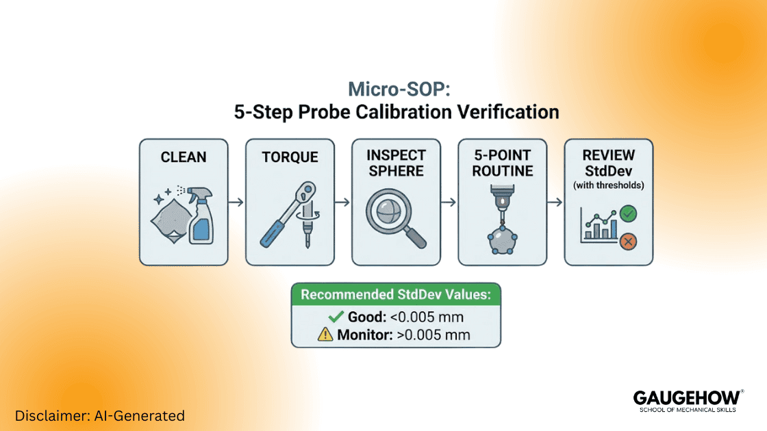
Execute this sequence before blaming the machine controller. 80% of field errors are probe-related.
1. Clean the Joints: Remove the stylus. Clean threads and mating faces with a lint-free cloth and isopropyl alcohol.
2. Torque Correctly: Use the manufacturer's quill tool. Finger-tight is insufficient. Over-tightening damages the piezo sensor.
3. Inspect the Master Sphere: Ensure the ceramic sphere is pristine. Check for flats, chipping, or oil.
4. Run the 5-Point Routine: Execute a standard calibration: one pole hit and four equator hits.
5. Review Standard Deviation (StdDev):
* < 0.005 mm: Probe is healthy.
* > 0.010 mm: Investigate for vibration or loose modules.
Log these results to trend probe behaviour over time.
Volumetric Compensation Explained
A standard 3-axis CMM is subject to 21 parametric errors:
Linear accuracy (3)
Rotational pitch, yaw, roll (9)
Straightness (6)
Squareness between axes (3)
Volumetric mapping quantifies these errors in a 3D grid. Compensation applies corrective offsets mathematically across the machine volume. Re-map after any crash or major maintenance event. Then, validate with an independent artefact like a length bar.
Calibration Cadence & Maintenance
Calibration is proactive maintenance, not just paperwork. Best practice scheduling prevents unplanned downtime.
Daily: Quick artefact check (ring gauge or sphere) for sanity verification.
Quarterly: Probe verification and program audits.
Annually: Full ISO 10360 lab calibration.
Critical Note: Always publish the measurement uncertainty with your results. Update this budget after hardware, probe, or software changes.
Two Micro Scenarios (Shop-Ready)
Scenario A — Production Line Drift
The Situation: The morning shift shows a slight drift in readings.
The Action: Run a 10-minute artefact check. If the standard deviation stays below 0.005 mm, continue production. If it rises, pause measurement and run full volumetric mapping.
Scenario B — Post-Crash Recovery
The Situation: A stylus hit the part hard. Subsequent parts show "lobing."
The Action: Run the Micro-SOP first. If the probe checks out, map the volume and reapply compensation. Do not resume production until validation artefacts pass.
Frequently Asked Questions (Technical Support)
General Troubleshooting
1. What are the 21 parametric errors in a CMM?
A rigid body has six degrees of freedom. A three-axis CMM therefore has 18 axis errors (3 × 6). Adding the three squareness errors between axes totals 21 parametric errors. Volumetric compensation maps and correct them to ensure accuracy.
2. How do you identify a "virtual probe" error?
A virtual probe error occurs when software offsets do not match the physical tip. Symptoms include the machine recording points in "air" or crashing before contact. Always rebuild the probe file after physical changes.
3. What is an acceptable probe standard deviation?
Most precision shops set alarm thresholds at 0.005 mm. Values consistently above 0.010 mm indicate vibration, loose modules, or a damaged sensor.
Advanced Technical Support
1. How does stylus length affect measurement uncertainty?
Long styli amplify errors. As the length increases, the stylus becomes less rigid. It bends slightly during contact before the trigger signal is sent. This "pre-travel" variation degrades accuracy. Keep styli as short and stiff as possible. If you must use a long extension (e.g., >100mm), use Carbon Fibre stems rather than steel to reduce droop.
2. What is the difference between Scanning vs. Touch-Trigger errors?
Touch-Trigger (Discrete) Errors usually stem from speed. Hitting the part too fast causes stem deflection and "lobbing" errors. Scanning Errors often stem from filtering. If the scan speed is too high, the machine captures surface roughness as form error. Lower the scan speed or increase the filter setting to smooth out the data.
3. What is the ISO 10360 standard,d and why do I need it?
ISO 10360 is the global gold standard for coordinate measuring machine errors. Unlike the older B89 standard, ISO 10360 tests the machine across its entire volume. It uses a series of length measurements (E0) and probing errors (PFTU). If your annual calibration certificate doesn't reference ISO 10360, you aren't getting a complete picture of your machine's health.
4. Can I use Methanol to clean my CMM scales?
No. Never use harsh solvents like Methanol or Acetone on open optical scales. These can strip the protective coating or damage the read-head glue. The safe bet is high-purity (>99%) Isopropyl Alcohol (IPA) and a lint-free cloth. Wipe in one direction only to push dust away from the sensor.
5. My Z-axis creates a "groan" noise. Is this an error?
Yes, this is a precursor to mechanical wear. That noise is usually the air bearings vibrating against the granite or a dirty counterbalance cylinder. Immediate action is required. Check the air supply pressure. If it drops below 5 bar (72 PSI), the bearings lose lift. If pressure is good, clean the guideways with IPA.
6. How do I calculate a basic Test Uncertainty Ratio (TUR)?
To ensure your measurement is reliable, compare your tolerance to your uncertainty. Use the formula: TUR = Part Tolerance / Expanded Measurement Uncertainty. Your goal is a TUR of 4:1 or better. If your tolerance is ±0.010 mm (total 0.020 mm), your measurement uncertainty must be 0.005 mm or less. If you are below 4:1, you cannot confidently pass borderline parts.
Mechanical Engineering Courses That Industry Actually Uses
Learn Tools of Design & CAD, Analysis & Simulation, Automation & Robotics, and Industry 4.0 used in modern factories.
Join 40+ Mech Courses like GD&T, Siemens NX, SolidWorks, CATIA V5, AutoCAD, ANSYS (FEA & Fluent), ABAQUS, Creo, Fusion 360, CNC Programming, Digital Twins, Python for Mechanical, and Industry 4.0.
Our Courses
Complete Course Library
Access to 40+ courses covering various fields like Design, Simulation, Quality, Manufacturing, Robotics, and more.


