CFD Boundary Conditions — Practical Inlet & Outlet Guide


Deepak S Choudhary
If you are staring at a run that “converged” but feels wrong, trust that feeling. Most bad CFD results are born at the edges. That is where your boundary conditions live.
You set an inlet, set an outlet, and hit solve. Then residuals drop. Plots look smooth. And later, someone asks the painful question: Did your cfd boundary conditions drive the answer?
This guide is built for you, and for that question. You will learn how to pick each inlet boundary condition and outlet boundary condition with confidence, then prove those choices are not biasing the result. You will also get a reusable BC table and a one-page audit checklist you can attach to any report.
What Boundary Conditions Really Mean
A CFD model is never the whole world. You always cut the domain somewhere. The solver cannot guess what happens beyond that cut. So you must tell it.
That instruction is a boundary condition.
Here’s the mindset that saves projects: the solver can only compute what you did not force. If you force the outcome by accident, you can still get a clean solution. It will just be the wrong story.
The Three Math Types, in Plain Language
Most boundary conditions fall into three families:
Fixed Value (Dirichlet): prescribe the boundary value, leaving no freedom.
Fixed Gradient (Neumann): prescribe the boundary flux, not the value.
Mixed (Robin): couple value and flux with a weighting.
You do not need heavy math here. You just need clarity: every boundary either pins a value, pins a flux, or mixes both.
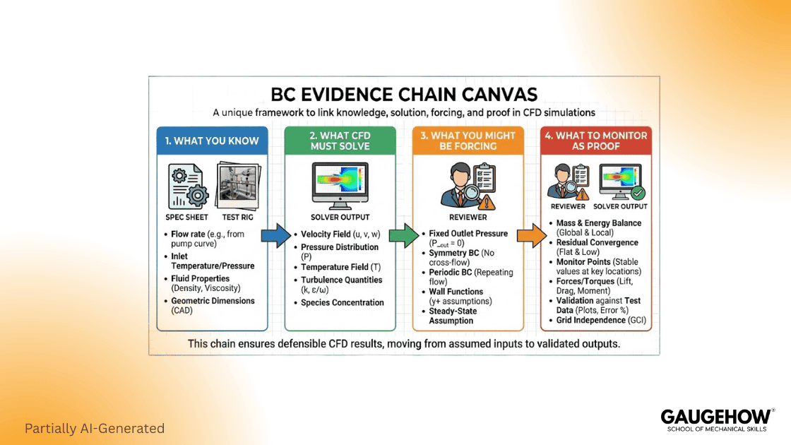
The Evidence Chain Method
Most top pages list boundary types. That helps you start. It does not help you defend.
Use this Evidence Chain for every cfd boundary conditions decision:
What do you actually know?
Measured flow, fan curve, ambient pressure, and temperature.What must CFD compute?
ΔP, force, flow split, mixing, heat transfer.What are you accidentally forcing?
Flow split, swirl, pressure recovery, and separation length.What will you monitor to prove you did not force it?
Mass imbalance, ΔP stability, outlet profile stability, and backflow fraction.
This is how senior reviewers think. They want evidence, not menus.
Inlet Boundary Conditions
Choosing an inlet is choosing what you trust most. Do you trust flow rate, pressure, or a measured velocity profile?
A simple rule works well:

If you know flow, use a flow-driven inlet.
If you know pressure, use a pressure-driven inlet.
Velocity Inlet
Velocity inlet is honest when you can justify the profile. Uniforms are rarely real, but they can still be acceptable. Just treat it as an assumption, and write it down.
Use a better profile when you can:
measured profile from the test
fully developed profile for long pipes
mapped profile from an upstream coarse model
Mass Flow Inlet
A mass flow inlet is ideal when the flow is controlled or measured. It locks the operating point. That is exactly what you want for a ΔP study.
But do not over-constrain. If you lock the flow at both ends, you can force the full solution. You might still “converge.” You will not be predictive.
If you are using a mass flow inlet boundary condition in Fluent, document your source and units clearly, and record whether it is total or per-area.
Pressure Inlet
A pressure inlet makes sense when upstream pressure is controlled. It is also useful when the flow direction may vary, but it is more sensitive to local recirculation near the boundary.
SimScale documents pressure inlet and outlet assignment, including hydrostatic profiles when gravity is enabled. (simscale.com)
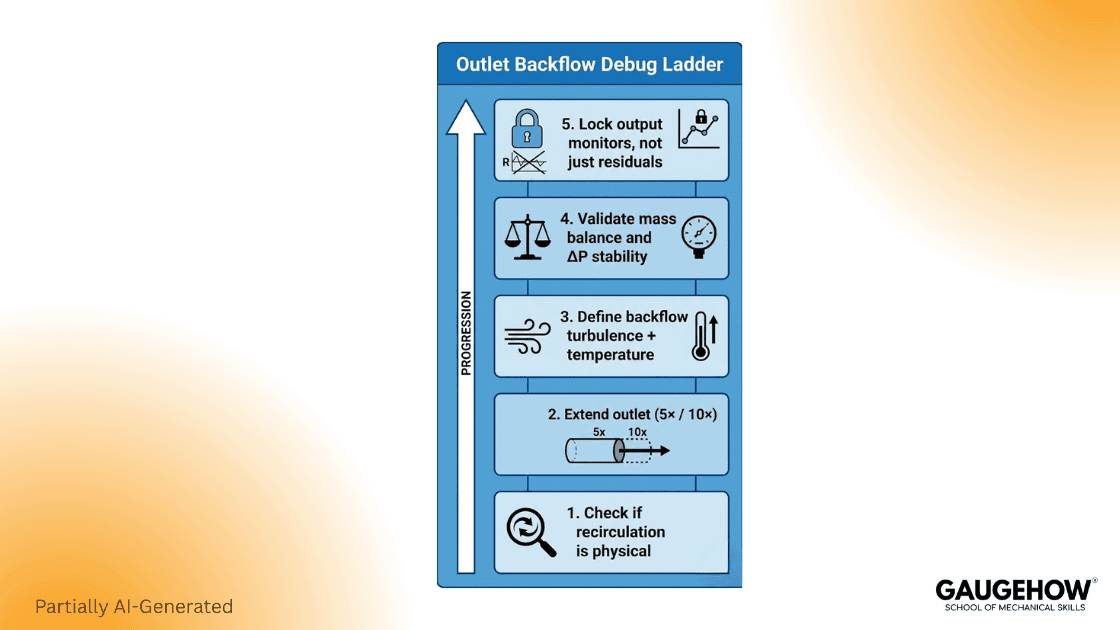
Outlet Boundary Conditions and Backflow
If your run diverges late or oscillates forever, your outlet boundary condition is a prime suspect. Many “numerics” problems are actually outlet placement problems.
Pressure Outlet
PA pressureoutlet is common because it sets a reference pressure. It also provides a place to specify scalars during backflow.
This matters because backflow can happen during iterations. Fluent guidance states that pressure outlet boundary conditions define static pressure at outlets and also define scalar variables “in case of backflow.” (Ansys Help)
If you are using a pressure outlet boundary condition in Fluent, you should set:
backflow turbulence method and values
backflow temperature and species, if relevant
backflow direction options when needed
Outflow
Outflow can look “clean,” but it assumes developed flow and weak downstream influence. If recirculation reaches the outlet plane, outflow can behave badly.
That is why many teams switch toa pressure outlet when the run misbehaves.
Geometry Extension Rule You Can Actually Use
Before you tune solver settings, check geometry.
A practical baseline is to extend inlets and outlets so the boundary plane sits in calmer flow. SimScale suggests an inlet length of about 5× inlet width and an outlet length of about 10× outlet width as a starting point in many internal cases. (simscale.com)
Worked Example 1: Pipe ΔP with Mass Flow Inlet
This is a reproducible baseline you can run in any solver. It also teaches you what “defensible” looks like.
Problem Setup
Fluid: water at 25°C
Density ρ ≈ 998 kg/m³
Pipe diameter D = 0.05 m
Pipe length L = 5 m
Mass flow rate ṁ = 2.0 kg/s
Target output: expected ΔP across the pipe
Step 1: Compute area
Step 2: Compute volumetric flow
Step 3: Compute mean velocity
Step 4: estimate expected ΔP
Use Darcy–Weisbach with a representative turbulent friction factor.
Take f = 0.02 as a reasonable first estimate.
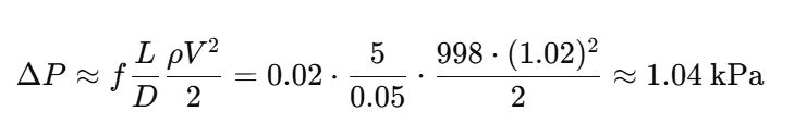
Your CFD result does not need to match this exactly. It must be in the same universe. If your CFD says 20 kPa, your setup is broken.
Boundary Conditions for This Case
Inlet: mass flow inlet at ṁ = 2.0 kg/s
Outlet: pressure outlet at gauge p = 0 Pa
Walls: no slip, smooth wall (first pass)
The BC table Entries you Should Record
Inlet type, mass flow value, units, source
Outlet type, gauge reference, backflow scalars
Wall type, roughness, thermal condition
Monitors You Must Track
Track these from iteration 1:
Mass imbalance or net mass flow error
ΔP between two planes
Outlet velocity profile or mass flow stability
Pass criteria
Mass imbalance is small and stable.
ΔP plateau is stable, not drifting.
Outlet profile stops changing materially.
If you need one strict check, use mass conservation first. That is the credibility gate.
What this Demonstrates
Outlet placement can bias ΔP.
Outlet extension often stabilises results.
A quick estimate anchors sanity early.
This section is designed as outreach fuel. It is “linkable” because it includes a dataset, a plot, and a one-page narrative.
Worked example 2: Bluff Body Farfield Setup
This example fixes a common pain: external domains that are too tight.
Problem Setup
Body: circular cylinder (bluff body)
Diameter D = 0.10 m
Fluid: air at 25°C, ρ ≈ 1.184 kg/m³
Freestream velocity U∞ = 15 m/s
Output: drag coefficient stability and wake sanity
Domain Sizing You Can Defend
A good first cut:
Upstream length: 5D
Downstream length: 15D
Top and bottom: 10D from the centerline
The intent is simple: the farfield boundary should not “push” the wake. If it does, you are simulating your box, not your cylinder.
Farfield Boundary Conditions
You can implement farfield in different ways, depending on the solver:
Option A: velocity inlet + pressure outlet
Upstream: velocity inlet U∞
Downstream: pressure outlet p = 0
Top and bottom: symmetry or slip, if justified
Cylinder: no slip wall
Option B: freestream style conditions (OpenFOAM style)
Use freestream velocity and freestream pressure patterns
Ensure consistent turbulence specification
Walls, Symmetry, Periodic
No slip walls
No slip is not just a toggle. It drives shear and near-wall gradients. If you cannot resolve the near-wall region, your wall model becomes the hidden boundary condition.
Slip and symmetry are not the same
Symmetry assumes a physical mirror plane.
Slip removes shear at a wall.
Use symmetry only when the physics is symmetric. If you use symmetry to hide 3D effects, your answer will look clean and be wrong.
Periodic boundaries
Periodic boundaries save compute. They also amplify mistakes. Ensure matching faces, consistent orientation, and correct driving conditions.
The 30-minute Boundary Audit
This is where your work becomes “review proof.” It also stops wasted runs.
A) Outside world reality
inlet matches operating point
The outlet reference is correct
properties match expected range
B) Over-constraint check
You are not fixing the flow and pressure everywhere
Backflow scalars are defined for a pressure outlet
C) Placement check
The outlet is away from the separation regions
The inlet is not feeding a distorted flow blindly
Farfield boundaries are far enough
D) Evidence and monitors
Conservation monitor chosen
decision output monitor chosen
One sanity profile chosen
BC table saved with the case
E) Change log discipline
Every boundary change has a reason
Record what moved, what stayed stable
OpenFOAM Fluent screenshot
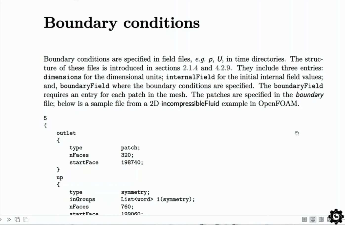

OpenFOAM’s inletOutlet boundary condition provides an outflow condition and applies a specified inflow value if return flow occurs. (doc.openfoam.com)
Common Mistakes and Fast Fixes
Mistake 1: Outlet too close to a bend
Symptom: reverse flow, oscillation, unstable pressure.
Fix: extend the outlet and move the plane downstream.
As a starting domain size, keep 5× inlet and 10× outlet lengths.
Mistake 2: Outflow used in non-developed flow
Symptom: unstable results, sensitive ΔP.
Fix: switch to a pressure outlet, then re-check placement.
Mistake 3: backflow scalars left unrealistic
Symptom: temperature or turbulence spikes at the outlet.
Fix: set backflow to ambient properties to prevent recirculation blowups.
Mistake 4: Symmetry used to hide real 3D physics
Symptom: unrealistically clean contours and wrong wake.
Fix: model the missing 3D region or justify symmetry.
Mistake 5: No one can reproduce your setup
Symptom: reruns depend on memory and luck.
Fix: publish the BC table and change log with every run.
FAQ
Which inlet should you use when you only know the flow rate?
Use a mass flow inlet, and pair it with a pressure outlet. That keeps the operating point honest.
Why does a pressure outlet show reversed flow?
Recirculation is the cause: the vortex reaches the outlet plane. Move the outlet downstream and set realistic backflow values.
Is a pressure outlet usually steadier than the outflow option?
Often, yes; it lets you prescribe reverse-flow scalars during backflow. That cuts outlet-triggered divergence.
How long should the inlet and outlet extensions be?
Start with 5× inlet width upstream and 10× outlet width downstream, then validate by tracking mass imbalance and key result drift until successive iterations change <1% consistently.
When is the inlet-outlet the right choice in OpenFOAM?
Use it on outlets that may see a brief reversal. It behaves as zero gradient on outflow, but switches to a specified inlet value when the flow flips back.
What is the fastest way to make your BCs defensible?
Fill the BC table once, run the boundary audit, and track the conservation plus one decision output monitor from the start.
Conclusion
Good boundary conditions do not feel clever. They feel honest. You tell the solver what you truly know, and you let it compute what you truly need. Then you prove your boundaries are not driving the answer.
If you do only three things after reading:
Fill the BC table and save it.
Run the 30-minute audit before serious runs.
Monitor conservation and one decision output.
Do that, and your cfd boundary conditions stop being a guess. They become engineering work.
Also Read:- What Is CFD? Computational Fluid Dynamics Explained Simply
CAD-CAM-CAE Work Platform
Find or Post CAD, CAM and CAE freelance projects, full-time jobs and Internships.
GaugeHow is the platform built for core engineering work. Whether you need a freelancer for a CAD project, a full-time hire, or an engineering intern,post it here and get matched with the right person.
Our Courses
Complete Course Library
Access to 40+ courses covering various fields like Design, Simulation, Quality, Manufacturing, Robotics, and more.


