Turbomachinery: Definition, Types, Core Equations, And Maps

Deepak S Choudhary
Call it turbomachinery when a rotating blade row exchanges shaft work with a moving fluid stream. Turbines pull power out, while compressors, pumps, and fans push power in to raise pressure or head. Use the same relations for scaling, map reading, and CFD credibility checks during design reviews.
If you are working on a turbomachinery problem, you usually need two things at once. You need a clean fundamentals picture, and you also need practical checks that survive a design review.
This page stays fundamentals first, and then it moves into the CFD decisions that most often decide whether results are defensible.
What Is Turbomachinery
Turbomachinery describes machines that transfer energy between a rotor and a continuously flowing fluid. You can think of it as one big family because turbines, compressors, fans, and pumps share the same energy transfer logic.
A turbine takes energy from the flow into the shaft, while a compressor sends shaft power into the gas, and a pump does that for liquids. Verify the sign with torque.
How Turbomachinery Is Classified
Classify first by work direction: turbines generate power; compressors, pumps, and fans consume it, which shows up as motor draw.
Classify next by the main flow path. Axial stages keep velocity mostly along the shaft, radial stages turn it across the radius, and mixed-flow stages sit in between for tight hardware packaging.
Impulse versus reaction tells you where the stage pressure change is taken. That matters for blade loading and where losses tend to concentrate.
Types And Where Each Fits
Most early selection is not about perfect design. It is about choosing the right machine family for your duty point.
Axial machines fit very high flow rates, and they tend to deliver lower head per stage, so staging is common in axial compressors. Radial machines fit a higher head per stage and compact packaging, which is why centrifugal pumps and many turbocharger compressors are so common. Mixed-flow is the compromise when axial length grows too much and a radial layout becomes heavy. It trades compactness against complexity.
A Simple Fit Table
Machine Family | Best Fit | Common Examples | Typical Risk |
Axial | Very high flow | Fans, axial compressors | Stall sensitivity |
Radial | Higher head per stage | Pumps, turbochargers | Surge and diffuser loss |
Mixed Flow | Balanced head and flow | Pumps, hydro runners | Off-design efficiency drop |
How Energy Transfer Really Happens
Work transfer comes from changing swirl, which changes angular momentum. Velocity triangles make that work term visible early, and catch wrong sign conventions, so you can spot bad assumptions before running CFD and wasting core hours.
If the swirl barely changes, the work term should stay small on that speed line. When your model claims a big pressure rise with near-zero swirl change, treat it as a sign error and recheck triangles, torque, and units.
Core Equations And Symbols
You do not need a wall of math to do good turbomachinery work. You do need a small set of equations that you can use for checks, scaling, and review conversations.
The Euler Turbomachinery Equation
The Euler turbine equation relates specific work to the change in tangential momentum through the blade row.
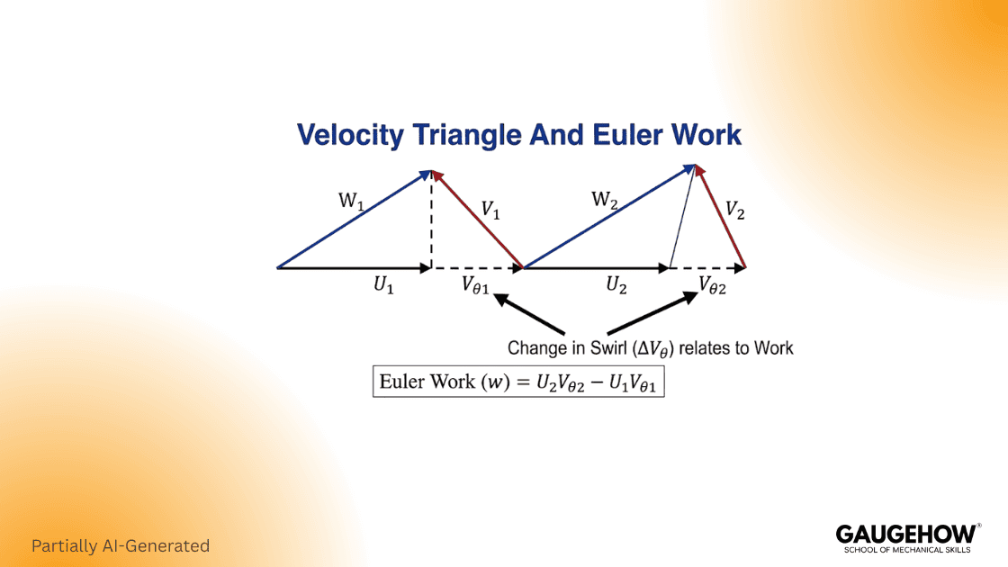
This equation applies across turbomachines, and it is the core physics link between blades and power transfer. (Massachusetts Institute of Technology)
Symbols Mini Box
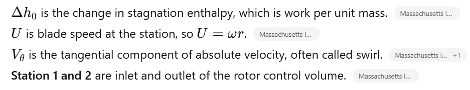
Sources:- Massachusetts Institute of Technology
Efficiency That Matches How People Report
For compressors and turbines, isentropic efficiency is the default metric because it compares real work to the ideal work at the same pressure ratio and inlet state.
Polytropic efficiency is common for compressors because it enables stage-by-stage comparison and multistage interpretation, especially at high overall pressure ratios and long trains.
Similarity, Specific Speed, And Selection
Similarity keeps scaling defensibly. Use it to move from one duty point to a whole machine family without guesswork, and to sanity check whether your selected size and RPM are physically credible.
Specific speed combines RPM, flow, and head into one selector, which lets you compare machines across sizes. Use it early to choose axial versus radial versus mixed concepts, then validate with limits like tip speed, pump cavitation margin, and compressor Mach sensitivity.
The Two Minute Sanity Check That Saves Reviews
Before detailed blading, write down five quick checks. Do it early, because it prevents unrealistic expectations from creeping in later.
Estimate tip speed and tip Mach, so compressibility risk is visible.
Estimate a flow coefficient so the incidence risk stays visible.
Estimate a loading or head coefficient, so the work demand is realistic.
Check the Reynolds trend, because low Reynolds cuts efficiency. (ScienceDirect)
Write an expected efficiency band from similar machines. (ScienceDirect)
Compressor Maps And Corrected Terms
A compressor map is the chart that relates pressure ratio to corrected flow, with corrected speed lines and efficiency islands.
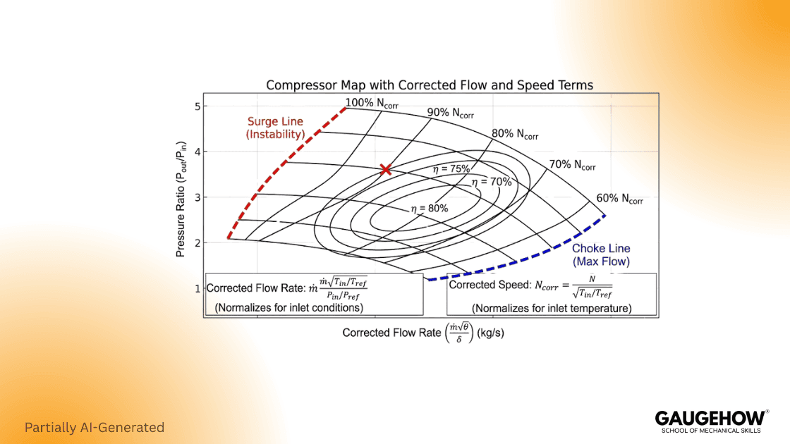
The left edge marks surge or stall risk, and the right edge marks choke, so you use the map to protect margin while reading off design behavior. Track distance to surge as a KPI, not just efficiency.
Corrected Terms Mini Box
Corrected flow and corrected speed exist to remove inlet day variation so aerodynamic similarity is preserved across tests and operating conditions.
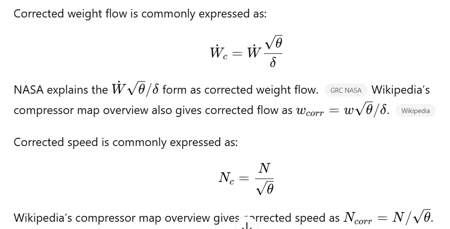
Here, theta is the temperature ratio to a reference condition, and delta is the pressure ratio to a reference condition. (Wikipedia)
Turbomachinery CFD Review Checks
CFD is powerful for trends and diagnosis, but it is also easy to make a clean-looking mistake. So the safest approach is to treat CFD as a review workflow, not just a solver run.
Start by stating your KPI clearly, like pressure ratio, torque, stage efficiency, or loss split. Then choose the interface model that matches the physics you need, and justify it in plain words.
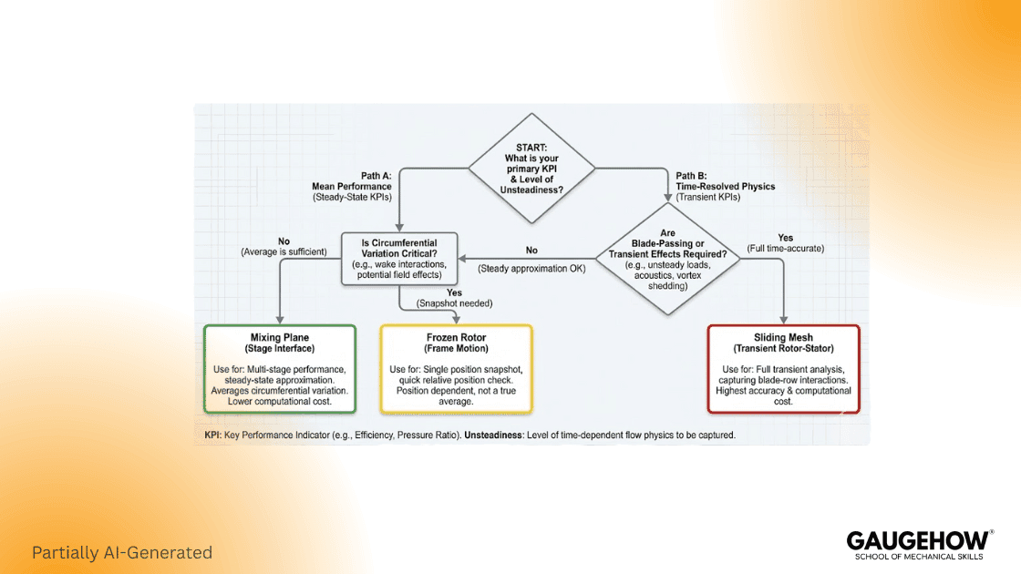
Rotor Stator Interfaces: Frozen Rotor, Mixing Plane, Sliding Mesh
Frozen rotor holds a fixed relative clocking, so it is mainly a startup tool to get a reasonable initial field. Results will shift with rotor stator alignment, so log the chosen clock angle as part of the case setup.
Mixing plane gives a steady interface by circumferentially averaging the profiles. It is usually the stronger baseline for steady performance work because it removes the blade-to-blade interaction detail while keeping stage mean quantities consistent.
Sliding mesh is the transient option. Use it when unsteadiness moves your KPI, such as blade passing force, tonal noise, or torque ripple, and budget for time step sensitivity.
Mixing Plane Averaging: Area, Mass, And Mixed Out
In the Fluent mixing plane, profile transfer can be averaged in three ways: area average, mass average, and mixed out.
A practical stability sequence is to begin with area averaging, then move to mass average or mixed out after any reverse flow clears. Otherwise, the latter options can struggle to converge when strong backflow is present at the interface.
A Review Safe CFD Checklist
Confirm rotation direction and work sign from triangles.
Track torque and pressure ratio until they are flat.
Show one mesh sensitivity sweep for one KPI.
State interface choice and why it matches the KPI.
Report corrected speed and corrected flow for map checks. (Wikipedia)
Real World Applications, With Two Useful Stats
Turbomachinery shows up in power, process, and mobility, and wind turbines are a clear example of scale effects.
DOE reports that in the United States in 2023, the average rated capacity of newly installed wind turbines was 3.4 MW, and the average rotor diameter was 133.8 meters. (The Department of Energy's Energy.gov)
DOE also states that a typical modern land-based wind turbine has blades of over 52 meters, and that GE’s Haliade X offshore wind turbine has blades about 107 meters long. (The Department of Energy's Energy.gov)
FAQ
What Is Turbomachinery
Call it turbomachinery when a rotating row trades shaft work with a fluid stream. That covers turbines, compressors, pumps, and fans, and the physics follows angular momentum, so track torque and swirl change to check power.
What Is The Most Defendable Rotor Stator Method
Build a defendable rotor stator model by starting with a mixing-plane average when your KPI is performance. Use frozen-rotor to seed a stable field, then switch to sliding mesh once unsteady blade passing shifts the KPI; watch torque ripple.
How Long Are Wind Turbine Blades
Use blade length as a quick scale check: land turbines often run over 52 m per blade, while large offshore units reach about 107 m. For planning, verify transport limits and tip speed.
Conclusion
By now, the picture should feel clear and usable. Turbomachinery is not just a definition, but a set of machine families with shared physics. You saw the types, the work transfer logic, and the few equations that anchor your intuition. Along with that, you now have the review safe CFD checks that stop results from drifting. We also covered tip clearance losses and Conjugate heat transfer, because those are where real projects fail quietly. If you want to build this skill faster, our CFD course walks you through the same workflow with templates and real turbomachinery cases.
CAD-CAM-CAE Work Platform
Find or Post CAD, CAM and CAE freelance projects, full-time jobs and Internships.
GaugeHow is the platform built for core engineering work. Whether you need a freelancer for a CAD project, a full-time hire, or an engineering intern,post it here and get matched with the right person.
Our Courses
Complete Course Library
Access to 40+ courses covering various fields like Design, Simulation, Quality, Manufacturing, Robotics, and more.


