Engineering Mechanics
Rigid Body vs Deformable Body in Engineering Mechanics
Stand on a steel beam. It bends. You cannot see it, a good beam might sag less than a millimetre, but it bends.
So here is the strange part. In your first engineering mechanics class, you are told to pretend it does not.
That pretending has a name, and understanding it is the whole point of rigid body vs deformable body in engineering mechanics. It is not a trick or a shortcut for lazy students. It is a deliberate engineering decision, and knowing when it holds and when it collapses is what separates someone who can pass an exam from someone who can design a part that does not fail.
What Is a Rigid Body in Engineering Mechanics?
A rigid body is a body we assume does not change shape or size when forces act on it. The distance between any two points inside it stays exactly the same, before loading and after.
No stretching. No bending. No twisting. No squashing.
Does such a body exist in real life? No. Every real material deforms a little under load. Steel, concrete, aluminium, all of them. A rigid body is an idealisation, a simplified model we agree to work with.
Everyday picture: imagine a solid brick. Push it, pull it, hang it from a rope. To your eye it looks exactly the same shape the whole time. It moves, but it never visibly changes form. That is close enough to rigid for us.
Because the shape never changes, rigid body mechanics only cares about two things:
Does the body move or stay still?
What forces and moments are acting on it?
That is why the entire subject reduces to force balance:
ΣF = 0 and ΣM = 0 for a body in equilibrium
Where ΣF is the sum of all forces in newtons (N) and ΣM is the sum of all moments in newton metre (N·m).
What Is a Deformable Body in Engineering Mechanics?
A deformable body is a body where the change in shape actually matters and we calculate it. Distances between points do change. The body stretches, compresses, bends or twists, and we want to know by how much.
Everyday picture: a rubber band. Pull it and you cannot pretend nothing happened. The stretch is the entire point.
But it is not just rubber. A real steel bridge girder, a car chassis in a crash, a bolt that is tightened to the edge of yielding, all of these are deformable bodies. The deformation is small, but small is not zero, and sometimes small is exactly what decides whether the part survives.
Deformable body mechanics adds new quantities that rigid body mechanics has never heard of:
Stress = force divided by area, measured in pascals (Pa) or more usefully N/mm² which is MPa
Strain = change in length divided by original length, a pure number with no units
Deflection = how far a point physically moves, in millimetres (mm)
Factor of safety = how much stronger the material is than it needs to be
This subject is what your syllabus later calls Strength of Materials or Mechanics of Solids.
Difference Between Rigid Body and Deformable Body
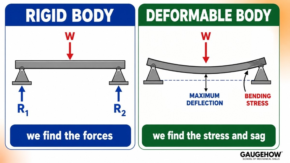
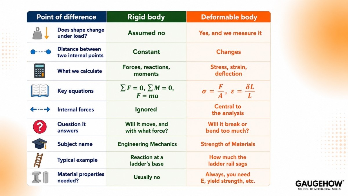
The cleanest way to hold it in your head:
Rigid body mechanics finds the forces. Deformable body mechanics checks whether the material can survive those forces.
They are not rivals. They are two steps of the same job, done in order.
Rigid Body and Deformable Body Examples
Treated as rigid
A ladder leaning on a wall. You want the reaction at the floor and the friction needed. The tiny bend in the rails changes nothing.
A crane holding a steady load. You want cable tension and whether the crane tips. Rigid is fine.
A truss in a roof. To find the force in each member, we treat every member as rigid.
A car being pushed along a road. For finding acceleration, the car is one rigid lump of mass.
A bolted machine frame. To find how much load each bolt takes, rigid works.
Must be treated as deformable
A diving board. The bending is the function. Ignore it and you have missed the entire device.
A rubber engine mount. It exists to deform and absorb vibration.
A car body in a crash test. Crumple zones are deformation, by design.
A spring in a suspension. Same story. Deformation is the job.
A long, thin column under compression. It can buckle sideways, and buckling is purely a deformation phenomenon.
Notice the pattern. When deformation is small and you only need the external forces, go rigid. When deformation is the point, or when it is what fails, you cannot.
Why Engineers Assume Bodies Are Rigid
Students often feel the rigid body assumption is cheating. It is not. There are three solid reasons for it.
1. The deformation really is tiny
A properly designed steel beam might deflect 5 mm over a 3 metre span. That is under 0.2 percent. When you are calculating a support reaction, changing the geometry by 0.2 percent changes your answer by roughly nothing. So we ignore it.
2. It makes the maths solvable by hand
Once a body can deform, the force distribution inside it depends on the deformation, and the deformation depends on the force. The two are tangled together. Solving that by hand for a whole structure is brutal. Assuming rigidity cuts the tangle and leaves you with clean force balance equations.
3. You need the forces before you can do anything else
Here is the part that clicks late for most students. You cannot calculate stress until you know the force. And to find the force, you use rigid body mechanics.
So the real workflow is:
Treat the body as rigid, apply ΣF = 0 and ΣM = 0, and find the reactions and internal member forces.
Take those forces into deformable body mechanics.
Calculate stress, compare against material strength, size the part.
Step 1 feeds Step 2. That is why engineering mechanics is taught before strength of materials, and why skipping it wrecks you later.
When the Rigid Body Assumption Breaks Down

The assumption is a tool, and every tool has limits. It fails in these situations, and a good engineer knows them by heart.
When deformation is the function of the part.
Springs, rubber mounts, diving boards, crumple zones, flexures, gaskets. If the part is meant to deform, you cannot assume it does not.
When the structure is slender.
Long thin columns buckle. A rigid body analysis will happily tell you a 3 metre steel rod can carry huge compression. In reality it bows sideways and collapses at a fraction of that load. Buckling is invisible to rigid body maths.
When deflection is a design limit.
A floor beam might be nowhere near breaking, but if it sags enough that people feel bouncy walking on it, the design has failed. Serviceability limits are deformation limits.
In statically indeterminate structures.
Some structures have more supports than equilibrium equations. A beam with three supports instead of two, for example. Here ΣF = 0 and ΣM = 0 simply do not give you enough equations. You are forced to bring in deformation compatibility to solve it. Rigid body mechanics alone hits a wall.
In vibration and dynamics of flexible parts.
A turbine blade or an aircraft wing flexes constantly. Its natural frequencies depend entirely on its stiffness, which is a deformable body property.
In impact. During a collision, deformation and energy absorption are the whole event.
How This Shows Up in FEA and CAD Software
This is where the two ideas stop being theory and start costing money.
In FEA, you choose your body type before you run anything. Most solvers let you flag a component as rigid so it does not deform, which cuts solve time massively.
Bolts, pins, fixture blocks and loading tools are often set as rigid because you do not care about stress in them, you only care about how they transfer load into the part you do care about.
Get that flag wrong and one of two things happens. Set a critical part to rigid and you will never see the stress concentration that would have failed it. Set everything deformable and your simulation takes hours to tell you what a hand calculation could have told you in five minutes.
There is also the quieter problem. Software will not tell you your loads and supports are wrong. It will just solve them beautifully. If your free body diagram was bad, the colourful contour plot on screen is confidently, expensively wrong.
That is the real reason this subject still gets taught before anyone touches a solver. If you want to see the transition from hand equilibrium to real 3D parts, FEA with ANSYS walks through static structural analysis from the ground up, and Fusion 360 has a built in static stress study you can run on your own CAD models to see deformation appear on a part you designed yourself.
Engineers who live in this space full time are usually working as CAE and simulation engineers, while those sizing real hardware from these numbers sit on the design engineer side.
FAQ
Q: What is the difference between a rigid body and a deformable body in engineering mechanics?
A: A rigid body is assumed not to change shape under load, so the distance between any two of its points stays constant. A deformable body does change shape, and we calculate that change as stress, strain and deflection. Rigid body mechanics finds the external forces and reactions. Deformable body mechanics then checks whether the material can survive them.
Q: Do rigid bodies actually exist?
A: No. Every real material deforms under load. The rigid body is an idealisation we adopt because the deformation is usually so small that ignoring it changes the force calculations by a negligible amount, while making the maths far simpler.
Q: Why is engineering mechanics based on rigid bodies?
A: Because you must know the forces before you can calculate stress. Rigid body analysis gives you the reactions and internal member forces, and those become the input to strength of materials. It is the first step of a two step process, not a simplification for beginners.
Q: When can I not use the rigid body assumption?
A: When deformation is the purpose of the part such as a spring or crumple zone, when the member is slender enough to buckle, when deflection itself is a design limit, in statically indeterminate structures, and in vibration or impact problems.
Q: Is a rigid body the same as a particle?
A: No. A particle has mass but no size, so moments do not apply to it and only ΣF = 0 is needed. A rigid body has real size and shape, so forces acting at different points create turning effects, which means you need ΣM = 0 as well.
Q: Which subject studies deformable bodies?
A: Strength of Materials, also called Mechanics of Solids or Mechanics of Deformable Bodies. It follows directly on from engineering mechanics and adds stress, strain, bending, torsion and buckling.
The Bottom Line
Rigid body vs deformable body in engineering mechanics is not a debate about which model is correct. Neither is correct. Both are useful, at different moments.
Assume rigid when you want to know what forces are acting. Switch to deformable when you want to know whether the part will survive them.
Almost every real engineering calculation does both, in that order. Learn to spot which stage you are in, and half the confusion in this subject disappears.
Want to see deformation on a real part? Run your first static stress study in Fusion 360, or go deeper with FEA with ANSYS. You can browse the full library at GaugeHow Courses.
Internal links used (all from GaugeHow catalog):
FEA with ANSYS: https://gaugehow.com/course/fea-finite-element-analysis-with-ansys
Fusion 360: https://gaugehow.com/course/fusion-360
CAE / Simulation Engineer track: https://gaugehow.com/cae-simulation-engineer
Design Engineer track: https://gaugehow.com/design-engineer
All Courses: https://gaugehow.com/course