Engineering Mechanics
Role Of Mechanics In Design In Engineering Mechanics
Ask a student how thick a steel bracket should be and you will usually get a guess. 10 mm sounds strong. 20 mm sounds safer.
Ask an engineer and you get a number, with a reason, and a note explaining exactly what would have to change for that number to change.
The gap between those two answers is the entire role of mechanics in design in engineering mechanics.
Mechanics is what turns "that looks about right" into "that is 16 mm, because the bending stress reaches 121 MPa and the yield strength is 250 MPa, giving a factor of safety of 2.06."
This article walks that path end to end, so you can see exactly where the equations you are learning turn into a real dimension on a real drawing.
What Is the Role of Mechanics in Design?
Design is a chain of decisions. Mechanics is what makes each link in that chain defensible rather than arbitrary.
Every part an engineer designs has to answer four questions:
What forces act on it? Mechanics answers this. Statics and dynamics.
What stress do those forces create inside it? Strength of materials answers this, using the forces mechanics gave it.
Can the chosen material survive that stress? Material properties answer this.
How much margin do we keep? Factor of safety answers this.
Notice question 1 comes first and everything else depends on it. If you get the forces wrong, every downstream calculation is wrong too. It does not matter how good your material data is or how expensive your simulation software is.
Mechanics is not one step in the design process. It is the step that makes every other step possible.
The Design Process: Where Mechanics Fits In
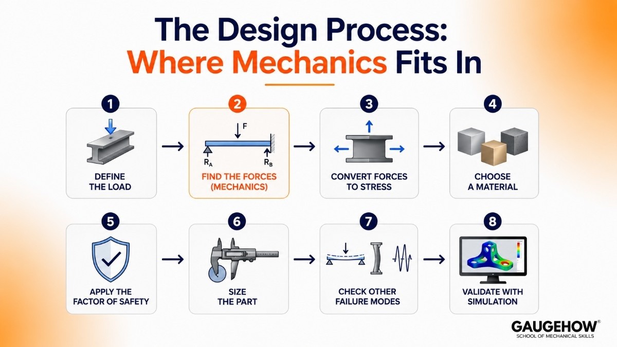
Real design follows a sequence. Here is where mechanics enters, and it enters early.
Step 1: Define the load
What does this part actually carry? A weight, a pressure, an impact, a vibration, a thermal load. This is the input, and it is where most bad designs are born, because engineers underestimate loads far more often than they miscalculate them.
Step 2: Find the forces (mechanics)
Draw the free body diagram. Apply ΣF = 0 and ΣM = 0 for static parts, or ΣF = ma for moving ones. Find every reaction, every internal force, every moment.
This is pure engineering mechanics. This is the subject you are studying right now.
Step 3: Convert forces to stress
Take those forces into strength of materials. Direct stress, bending stress, shear stress, torsional stress.
σ = F/A for direct stress, or σ = M/Z for bending, where Z is the section modulus.
Step 4: Choose a material
Compare the stress you calculated against the strength of candidate materials. Steel, aluminium, cast iron, plastic.
Step 5: Apply the factor of safety
Never design to the limit. Divide the material strength by a safety factor and design to that lower allowable stress instead.
Step 6: Size the part
Now the geometry falls out. Thickness, diameter, cross section. The number is not chosen. It is derived.
Step 7: Check other failure modes
Yielding is not the only way things break. Check deflection, buckling, fatigue.
Step 8: Validate with simulation
Now, and only now, run FEA. Not to find the answer, but to confirm the answer you already estimated by hand.
From Load to Size: A Real Worked Example

Theory is cheap. Let us actually size a bracket.
The problem. A steel bracket sticks out from a wall like a shelf. A 500 N load hangs from its free end, 100 mm from the wall. The bracket is 10 mm wide. How deep does it need to be?
Step 1: Find the force and moment (mechanics)
The load creates a bending moment at the wall, which is the most stressed point.
M = F × d = 500 N × 100 mm = 50,000 N·mm
Step 2: Decide the allowable stress
Mild steel has a yield strength of about 250 MPa. We will use a factor of safety of 2.
Allowable stress = 250 ÷ 2 = 125 MPa (which is 125 N/mm²)
Step 3: Find the section modulus needed
Bending stress is σ = M / Z, so rearranging:
Z required = M ÷ σ = 50,000 ÷ 125 = 400 mm³
Z is the section modulus, a purely geometric property that describes how well a shape resists bending. Units are mm³.
Step 4: Turn that into a dimension
For a rectangular section, Z = b·h² / 6, where b is width and h is depth, both in mm.
400 = (10 × h²) ÷ 6
h² = (400 × 6) ÷ 10 = 240
h = 15.5 mm
Step 5: Round up and verify
Use 16 mm. Now check backwards.
Z actual = (10 × 16²) ÷ 6 = 2560 ÷ 6 = 426.7 mm³
σ actual = 50,000 ÷ 426.7 = 117.2 MPa
Factor of safety = 250 ÷ 117.2 = 2.13 ✓
Done. The bracket is 16 mm deep, and you can defend that number to anyone who asks.
What happens if you guess instead
Suppose someone "eyeballs it" and picks 12 mm because it looks sturdy.
Z = (10 × 144) ÷ 6 = 240 mm³ σ = 50,000 ÷ 240 = 208 MPa
Factor of safety = 250 ÷ 208 = 1.2
That is dangerously thin. A 20 percent overload, one person leaning on it, and the bracket yields permanently. It might not snap, but it will bend and never come back.
The guess did not look wrong. It looked reasonable. That is what makes guessing dangerous.
Factor of Safety: The Number That Decides Everything
The factor of safety (FoS) is how much stronger a part is than it strictly needs to be.
FoS = Material strength ÷ Actual working stress
An FoS of 2 means the part could take double the expected load before it begins to yield.
Why not just design to the exact limit?
Because reality is not tidy.
Loads are estimated, and users overload things
Material properties vary batch to batch
Manufacturing introduces flaws
Corrosion and wear degrade parts over time
Your own calculation contains simplifications
The factor of safety absorbs all of that uncertainty in one number.
The trade-off mechanics reveals
Look at aluminium versus steel. Similar yield strength, one third the density.
So aluminium is always better? No. Its Young's modulus is about 70 GPa against steel's 200 GPa, meaning it is roughly three times more flexible.
An aluminium bracket of the same size will not break, but it will visibly sag. If deflection matters, and it usually does, you need a bigger section, which eats into the weight saving.
That trade-off only becomes visible because mechanics separated the two questions: will it break and will it bend too much. Those are different failure modes, and a material can pass one while failing the other.
How Mechanics Decides Shape and Cross Section
Here is one of the most satisfying results in all of engineering, and it comes straight from a moment of inertia calculation.
Where you put the material matters more than how much you have.
Why the I-beam exists
In bending, stress is highest at the top and bottom surfaces of a beam and drops to zero at the neutral axis in the middle. The material sitting near the centre is doing almost nothing. It is carrying weight and cost for no structural return.
So remove it. Keep the flanges at the top and bottom where the stress lives, and connect them with a thin web.
That is an I-beam. Same steel, far more bending resistance per kilogram. Not a clever aesthetic choice. A direct consequence of the second moment of area.
Why bicycle frames and scaffolding use hollow tubes
Same logic, applied to a circle. In bending and torsion, the outer material does the work and the core is nearly idle.
And the payoff scales brutally. For a solid round section, the second moment of area I = πd⁴ / 64. That fourth power means doubling the diameter multiplies bending resistance by 16.
So a slightly larger hollow tube massively outperforms a smaller solid rod of equal weight. Every bicycle frame, scaffold pole, aircraft spar and drone arm on earth is that equation, built.
The design rule that follows
To make a part stiffer, changing its shape is almost always cheaper than adding material or upgrading the material. Mechanics is what tells you that, and it is why experienced designers reach for a rib or a flange before they reach for thicker steel.
Failure Modes Mechanics Helps You Prevent
Yielding is the failure students think about. It is one of at least four.
Yielding. Stress exceeds the material's yield strength and the part deforms permanently. Checked with σ = F/A or σ = M/Z.
Excessive deflection. The part does not break, but it bends so much it stops working. A floor beam nowhere near breaking can still feel bouncy enough to fail the design. A machine tool that flexes under cutting load will not hold tolerance.
Buckling. A slender column under compression bows sideways and collapses at a load far below its yield strength.
This is the one that catches people, because a pure strength calculation says the column is fine. Long, thin and in compression is the danger combination.
Fatigue. A part subjected to millions of small load cycles fails at a stress well below yield. Most real mechanical failures in service are fatigue failures, not overload failures.
The part did not break because the load was too big. It broke because the load happened too many times.
A design that only checks yielding is not a finished design. It is a first check.
Mechanics vs Software: What CAD and FEA Cannot Do For You
Modern design lives in software, and it is worth being precise about what software does and does not solve.
What FEA does well. Solves equilibrium at thousands of nodes simultaneously. Handles complex geometry no hand calculation can touch. Shows you exactly where stress concentrates.
What FEA cannot do.
It cannot tell you the load was wrong
It cannot tell you a support should have been free to rotate
It cannot tell you the unit system was inconsistent
It cannot tell you the result is physically implausible
The solver does not think. It takes what you gave it, solves it perfectly, and returns a beautiful, detailed, colourful, entirely wrong answer without a single warning.
The engineer who catches that is the one who estimated the answer by hand first. If your hand calculation says 120 MPa and the software says 2,400 MPa, something is wrong with the setup, and you will find it. If you never did the hand calculation, you have nothing to compare against and you will simply believe the screen.
This is the real reason engineering mechanics is still taught before anyone is allowed near a solver. Not tradition. Quality control.
You can see the whole loop, hand calculation then simulation, in a Fusion 360 static stress study, and go much deeper into structural analysis with FEA with ANSYS. This is the daily work of a CAE and simulation engineer, while turning those numbers into manufacturable hardware is the job of a design engineer.
Design Mistakes That Come From Weak Mechanics
These are the ones that show up again and again in real projects.
Underestimating the load. The most common and most expensive. A shelf rated for books gets loaded with tools.
Ignoring dynamic effects. A load applied suddenly can produce roughly double the stress of the same load applied gradually. Design for the static case only, and an impact will find you.
Forgetting stress concentration. A sharp internal corner, a keyway, a sudden change in section. Stress spikes locally, often by a factor of 2 or 3. This is why designers add fillets, and why a sharp corner is a crack waiting to start.
Checking only strength, never stiffness. The part survives but flexes too much to function.
Missing buckling. Long slender compression member passes the stress check and collapses anyway.
Over-designing out of fear. Heavier, costlier, and in moving systems, permanently worse.
Every one of these traces back to a mechanics step that was skipped or rushed.
FAQ
Q: What is the role of mechanics in design?
A: Mechanics determines the forces and moments acting on a part, which is the first and most fundamental step in design.
Those forces become stresses, stresses drive material selection, and combined with a factor of safety they determine the final dimensions. Without mechanics, every design decision downstream is a guess.
Q: How do engineers decide how thick a part should be?
A: They calculate the internal force or bending moment using mechanics, divide the material strength by a factor of safety to get an allowable stress, then work backwards from the stress formula to find the required section. The dimension is derived, not chosen.
Q: What is a factor of safety and what value should I use?
A: It is material strength divided by working stress. Typical values are 1.5 to 2 for well understood static loads, 3 to 5 for shock or impact, and 4 to 8 for lifting equipment where human life is at risk.
Higher is not automatically better, because over-designed parts are heavier and more expensive.
Q: Why is an I-beam stronger than a rectangular beam of the same weight?
A: In bending, stress is greatest at the top and bottom surfaces and zero at the neutral axis in the centre. An I-beam removes the near-useless material from the middle and concentrates it in flanges where the stress is highest, giving far more bending resistance per kilogram.
Q: Does FEA software replace hand calculations?
A: No. FEA solves equations extremely fast but cannot detect wrong loads, wrong supports or inconsistent units. A hand estimate is what tells you whether the simulation result is believable. Engineers who skip the estimate have no way to catch a bad setup.
Q: What is the most common design mistake?
A: Underestimating the load. Calculation errors are relatively rare, but assuming a part will only ever see the load you intended is extremely common, and real users routinely exceed it.
The Bottom Line
The role of mechanics in design is to replace opinion with a number you can defend.
It gives you the forces. Everything else in design, stress, material, thickness, safety margin, is downstream of that one output.
It tells you where to put the material. The I-beam and the hollow tube exist because a moment of inertia calculation said so.
It tells you when to distrust your software. Which, in an industry where every answer arrives in colour, is worth more than ever.
That 16 mm bracket was not a guess. It came out of a moment, a stress, a material and a safety factor. Learn to walk that path and you stop being someone who checks designs, and start being someone who makes them.
Ready to design something and prove it works? Run a static stress study in Fusion 360, take it further with FEA with ANSYS, or explore the full GaugeHow course library.
Internal links used (all from GaugeHow catalog):
Fusion 360: https://gaugehow.com/course/fusion-360
FEA with ANSYS: https://gaugehow.com/course/fea-finite-element-analysis-with-ansys
CAE / Simulation Engineer track: https://gaugehow.com/cae-simulation-engineer
Design Engineer track: https://gaugehow.com/design-engineer
All Courses: https://gaugehow.com/course.