
Common Engineering Drawing & GD&T Interview Questions


Deepak S Choudhary
Learn More in This Video
Subscribe to GaugeHow for More
Engineering drawing and GD&T turn part intent into a manufacturable, inspectable contract. This Q&A guide covers orthographic and isometric views, first vs third angle projection, datums, tolerance vs allowance, feature control frames, position, MMC/LMC, runout, and surface roughness (Ra). It finishes with 40 high-intent questions.
Engineering drawing is the standard way to communicate geometry, size, and allowable variation so a part can be made and verified. GD&T tightens that language so functional features assemble the same way every time.
Have you ever looked at a drawing that “seems clear,” but the shop, QC, and design team still interpret it three different ways?
This guide keeps the answers short and practical across projections, datums, dimensioning logic, key GD&T symbols, MMC/LMC behavior, and surface finish so you can read prints faster and avoid the common traps.
Projections & Views (Q1–Q11)
Q1. What is an engineering drawing actually meant to communicate?
A drawing communicates shape, size, allowed variation, and verification intent. In other words, it is the contract between design, manufacturing, and inspection, not just a picture of the part.
Q2. What is orthographic projection?
Orthographic projection represents a 3D object using multiple 2D views where projection lines are perpendicular to the view plane.
It is used because it preserves true sizes for features that sit parallel to the plane.
Q3. Which views are considered the “principal” views?
Most prints start with the front, top, and right side as the principal set. From there, you add section or detail views only where internal geometry or small features need clarity.
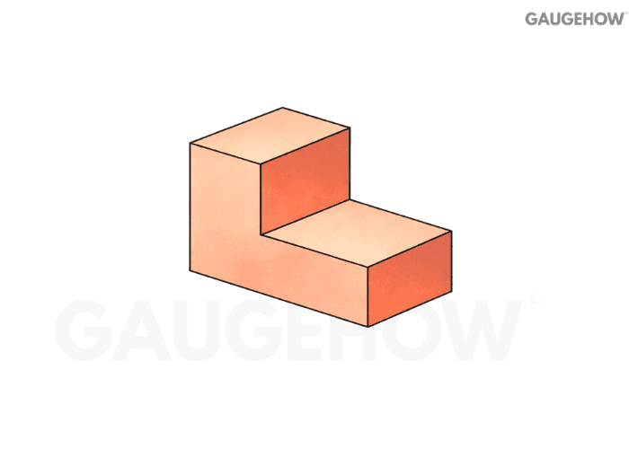
Q4. What is an isometric view used for?
Isometric is a pictorial view that helps you visualize the 3D form quickly. It supports understanding, but it usually does not replace orthographic views for manufacturing dimensions.
Q5. Orthographic vs isometric: what information does each hide or reveal?
Orthographic gives true geometry per view, but forces you to mentally assemble the 3D shape. Isometric shows “3D at once,” but lengths are not interpreted like separate true views for dimension control.
Q6. How do you decide the minimum set of views for a part?
Start from the manufacturing and inspection risk, not from “how many faces it has.”
Pick the front view that shows the most features with the fewest hidden lines.
Add the view that reveals the critical thickness/height that the front view cannot show.
Use a section view when internal geometry drives function or tolerance.
Add a detail view only for small features that would force cluttered dimensions.
A clean print uses the fewest views that still remove ambiguity.
Q7. What is a section view, and why does it reduce ambiguity?
A section view “cuts” the part so internal features become visible without hidden-line confusion. It prevents wrong machining choices on pockets, bores, ribs, and wall thickness.
Q8. What is the difference between first-angle and third-angle projection?
They differ in how views are placed relative to the front view. The object is conceptualized differently with respect to the projection plane, so the top and side views swap placement logic.
Q9. How do you identify first-angle vs third-angle quickly on a drawing?
Do not guess from view placement alone. Use the projection symbol and then sanity-check the layout.
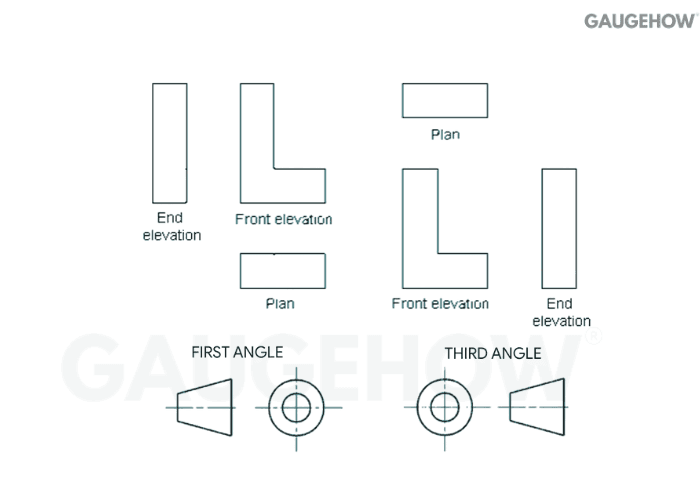
Find the angle-of-projection symbol on the title block or notes.
Confirm that the top and right-side views match the symbol logic.
If views look “flipped,” assume a projection system mismatch before blaming the model.
That small symbol prevents expensive mirrored parts.
Q10. How Do You Draw A Circle In Isometric View (Four-Centre Method)?
In isometric, a true circle appears as an ellipse, so the four-centre method approximates that ellipse using four tangent arcs.
Draw an isometric “square” (a rhombus) with a side equal to the circle diameter, mark the midpoints of all four sides, then locate the four arc centers using the standard four-centre construction lines inside the rhombus. Finally, draw four smooth tangent arcs between the midpoints to complete the isometric circle.
Q11. What Do Common Drawing Symbols Mean (Ø, R, SR, Depth, Countersink/Counterbore, Surface Finish, Datum, MMC/LMC)?
Ø means diameter, and it must precede any diametral size. R is radius, while SR is spherical radius for a spherical feature. The depth symbol marks how deep a drilled or machined feature must go from the referenced surface.
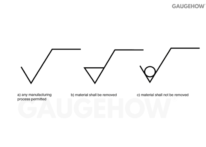
Countersink indicates a conical recess (typical for flat-head seating), while counterbore/spotface indicates a flat-bottom recess (typical for socket-head seating). The surface finish symbol with an Ra value sets the required roughness level on that face.
A datum feature symbol tags the feature used to establish a datum reference frame.
MMC (Ⓜ) and LMC (Ⓛ) are material-condition modifiers that change how geometric tolerance is applied, and MMC often enables bonus tolerance when the feature departs from MMC.
Datums & Dimensioning (Q12–Q24)
Q12. What is a datum in GD&T terms?
A datum is a theoretically perfect reference (plane/axis/point) used to locate and orient other features.
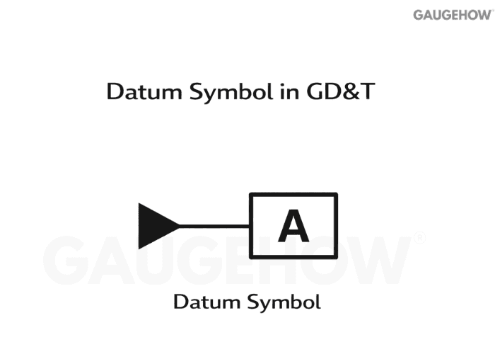
It is not “just any surface,” it is the agreed measurement origin.
Q13. What is the difference between a datum feature and a datum?
A datum feature is the real physical surface or hole on the part. The datum is the ideal reference derived from that feature during setup and inspection.
Q14. What does “datum reference frame” mean?
A datum reference frame is the ordered set of datums (primary, secondary, tertiary) that locks down all degrees of freedom. It defines how the part is fixtured conceptually for measurement.
Q15. How do you choose good datums for a part?
Treat datum selection as a functional fixturing problem.
Choose the surface that actually seats in the assembly as the primary datum.
Use the feature that controls clocking/rotation as the secondary datum.
Pick the feature that controls the final location as the tertiary datum.
Prefer datums that are stable, accessible, and inspectable.
A bad datum scheme creates “perfect parts” that still fail assembly.
Q16. Which statement best explains the concept of a horizontal datum?
A horizontal datum is the reference plane you treat as “level” for the part, so other features are oriented from it. In practice, it is the plane your setup rests on when you care about top and bottom geometry alignment.
Q17. What are basic dimensions (boxed dimensions), and why are they used?
Basic dimensions define the theoretically exact location, size, or orientation of a feature. GD&T then controls how far the real feature is allowed to deviate from that exact target.
Q18. Tolerance vs allowance: what’s the difference?
Tolerance is permitted variation on a single dimension. Allowance is the intended difference between mating parts at maximum material condition, setting up minimum clearance or maximum interference.
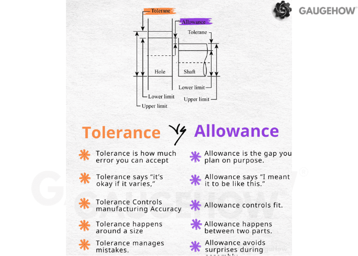
Q19. Allowance vs tolerance vs clearance: how do you keep them straight?
Think “variation” vs “fit intent” vs “actual gap.”
Tolerance: how much a single size may vary.
Allowance: the planned tightest fit condition between two mating parts.
Clearance: the actual positive gap after real sizes stack up.
Interference: the actual overlap when the shaft ends up larger than the hole.
This language matters because it changes how you specify and inspect functional fits.
Q20. When should you use unilateral vs bilateral tolerances?
Unilateral makes sense when variation is only acceptable in one direction, like a minimum wall thickness or a maximum protrusion. Bilateral works when deviation on both sides is functionally acceptable.
Q21. What is limit dimensioning, and when is it better than ±?
Limit dimensioning directly states max and min values. It is clearer for production because it removes arithmetic and reduces interpretation errors on the shop floor.
Q22. What is tolerance stack-up, and when should you worry about it?
Stack-up is the combined effect of multiple tolerances across an assembly chain. It becomes critical when many dimensions align in one functional direction, like locating a bolt pattern to a sealing surface.
Q23. “Is there a maximum value a radius can have?” What does R MAX mean on drawings?
R MAX sets an upper limit on the radius, usually to prevent over-blending that would violate mating geometry or reduce contact area. It is a control statement, not a suggestion.
Q24. “What does' cylinder coaxial with the Y axis mean?”
It means the cylinder’s axis is intended to lie on the defined Y-axis direction of the coordinate system or datum reference frame. Practically, you are controlling the orientation and location of that axis relative to the chosen references.
GD&T Essentials (Q25–Q40)
Q25. What is GD&T, and why not just use ± dimensions everywhere?
GD&T controls geometry in a way that matches real function: form, orientation, and location relative to datums. ± Dimensioning alone often over-constrains parts or leaves gaps in inspection interpretation.
Q26. What is a Feature Control Frame, and how do you read it fast?
Read it in a fixed order so you never miss modifiers.
First cell: the geometric characteristic symbol (flatness, position, runout, etc.).
Next: the tolerance value and whether it is diametric.
Then: any material condition modifier (MMC/LMC/RFS).
Last: the datum sequence (A, then B, then C) and any datum modifiers.
Once that sequence becomes automatic, print reading speeds up immediately.
Q27. What is a tolerance zone in GD&T?
A tolerance zone is the allowed region where the feature must lie, such as two parallel planes for flatness or a cylindrical zone for position on a hole axis. It is geometry-based, not just a numeric ± band.
Q28. What does flatness control?
Flatness controls how much a surface can deviate from a perfect plane, without referencing any datum.
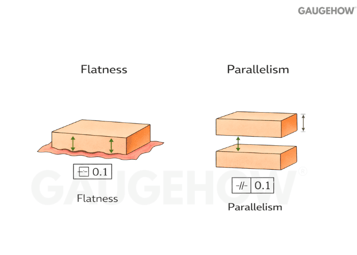
It is purely a form control.
Q29. What does parallelism control?
Parallelism controls how parallel a surface or axis is relative to a datum. It is an orientation control, so it depends on a reference.
Q30. Perpendicularity vs angularity: what’s the difference?
Perpendicularity controls a 90° relationship to a datum. Angularity controls a specified non-90° angle, still relative to a datum reference.
Q31. What does position tolerance control?
Position controls the allowed variation of a feature’s location, typically a hole or slot, relative to datums.

It often controls both the location and orientation of the axis when applied correctly.
Q32. How do you interpret a position tolerance with datums A, B, and C?
Anchor your thinking to set up order and what each datum “locks.”
Datum A usually establishes the primary seating plane.
Datum B typically controls rotation or side location.
Datum C finalizes the last translational lock.
The position tolerance defines the zone the feature axis or center must stay within after that datum alignment.
If the datum order is wrong, the part can be inspected as “good” and assembled as “bad.”
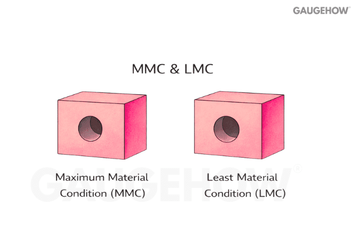
Q33. What are MMC and LMC in plain terms?
MMC is the size condition with the most material: the smallest hole or the largest shaft. LMC is the least material: the largest hole or the smallest shaft.
Q34. Position At MMC + Bonus Tolerance: What Changes In Practice?
Bonus tolerance is the extra location tolerance you gain when the actual feature size moves away from MMC. It is used because assembly cares about worst-case material, so the standard allows more positional freedom when you “buy back” clearance.
Micro-example (one line, numeric): If a hole is Ø10.00 ±0.10, then MMC = Ø9.90. If position is Ø0.20 at MMC (M) and the produced hole measures Ø10.05, bonus = 10.05 − 9.90 = 0.15, so total allowed position = Ø0.20 + Ø0.15 = Ø0.35.
Q35. When should you use MMC or LMC on position?
MMC is common when assembly relies on worst-case fit, like bolt patterns and pins, where functional gaging makes sense. LMC shows up when the minimum wall thickness or minimum material around a feature is the real risk.
Q36. Circularity vs cylindricity: what’s the difference?
Circularity controls roundness in each cross-section. Cylindricity controls the entire cylinder surface as a 3D form, combining straightness and circularity behavior.
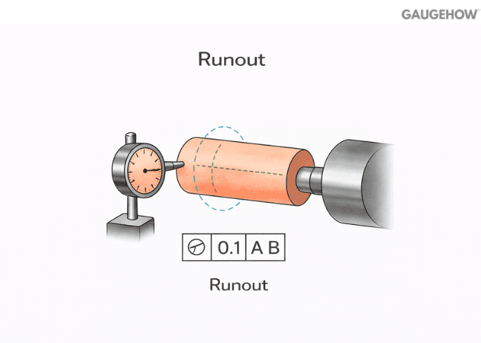
Q37. What is runout, and how do circular and total runout differ?
Circular runout checks the variation at a single cross-section during rotation. Total runout controls variation across the full length of the rotating surface, making it stronger for shafts and bearing seats.
Q38. Profile of a line vs profile of a surface: when do you choose each?
Profile of a line controls a 2D cross-section boundary, useful when a slice matters most. Profile of a surface controls the full 3D skin, great for castings, aero surfaces, and blended forms.
Q39. Why are concentricity and symmetry avoided on many modern prints?
They are hard to measure reliably and often don’t map cleanly to functional requirements. Designers usually replace them with position, profile, or runout controls that inspection can verify with less ambiguity.
Q40. Surface Roughness Ra: How Is It Measured And Calculated?
Surface roughness callouts control how smooth a functional surface must be so it seals, slides, wears, or bonds as intended. Ra is the arithmetic average roughness of the measured profile over an evaluation length, and instruments compute it from the sampled surface trace.
Micro-example (callout + what shop measures): If a drawing calls Ra 1.6 µm max on a sealing face, the shop typically checks it with a stylus profilometer on the actual contact zone, and the instrument reports Ra from the filtered profile data.
How Ra is calculated (keep it simple):
Ra = (1/L) ∫0^L |y(x)| dx Here, y(x) is the profile height relative to the mean line, and the device computes this from many sampled points rather than you hand-calculating it.
Common misread that causes rejects: Ra is not peak-to-valley height (that is, a different parameter, often Rz), and unit mix-ups happen all the time, so µm vs µin must be read exactly as specified.
Conclusion
Engineering drawing and GD&T are not about making the print look complete. They are about removing interpretation, so manufacturing, assembly, and inspection all make the same part for the same functional reason. Once you read drawings through that lens, orthographic and isometric views become a clarity tool, datums stop being labels and start behaving like setup logic, and GD&T symbols turn into controlled tolerance zones instead of “extra rules.”
If you want this to translate into real outcomes, build one habit: always ask what the feature must do in assembly, then choose the view, datum scheme, and control that makes that behavior measurable. When the drawing matches how the part is fixtured and verified, you stop losing time in shop-floor debates, and you stop shipping parts that technically meet dimensions but still fail fit.


