
Machine Design Interview Questions


Deepak S Choudhary
Learn More in This Video
Subscribe to GaugeHow for More
Machine design is the engineering of components, so they transmit power, carry load, and survive real service without yielding, fatigue cracking, or wear-out. This guide covers failure theories, fatigue and endurance limit, stress concentration, shafts, keys, couplings, bearings, gears, springs, and fits, using 40 interview-ready questions with short, practical answers.
Machine design is the discipline of sizing and detailing parts so they do the job repeatedly, with a predictable safety margin. It converts loads, geometry, and material limits into dimensions, tolerances, and checks.
Ever designed a shaft that looked safe on paper, but failed at the keyway or shoulder after a few weeks because the loading was cyclic and the geometry had a stress riser?
This guide is a focused Q&A set on the exact decision points engineers get asked about: which failure theory to use, how to treat fatigue and mean stress, how to think about stress concentration, and how to choose shafts, keys, couplings, bearings, gears, springs, and fits without over-explaining.
Questions & Answers
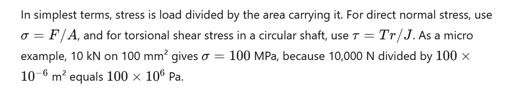
Q1. How to find stress?
Q2. What is stress concentration?
Geometry changes like holes, keyways, grooves, and shoulders raise local stress above nominal. That is why cracks often start at a fillet or notch, even when the average stress looks safe.
Q3. What is a stress riser?
A stress riser is any feature that spikes local stress, especially under cyclic loads. Keyways, snap-ring grooves, sharp internal corners, and poor undercuts are common culprits.
Q4. How to calculate the stress concentration factor?
Use
Compute nominal stress from basic formulas, then obtain Kt from standard geometry charts or a clean elastic FEA model with consistent boundary conditions.
Q5. How to find the stress concentration factor?
Start by identifying the feature type, then form the relevant ratios like (D/d) and (r/d). Read Kt from charts for the closest matching case, and validate with FEA when the geometry deviates from textbook shapes.
Q6. Which failure theory should you use for ductile parts under static combined stress?
Use Von Mises or Tresca for ductile metals because yielding correlates better with shear-driven distortion than peak normal stress.
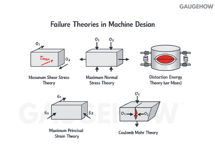
Von Mises is widely used; Tresca is typically more conservative.
Q7. What is Von Mises theory?
Yielding begins when the equivalent distortion-energy stress reaches the yield strength, so design checks compare
Q8. What is the Tresca theory, and when is it conservative?
Tresca predicts yield when the maximum shear stress reaches the shear yield level. It often gives a safer result than Von Mises for multiaxial stress states.
Q9. When does maximum principal stress theory make sense?
Brittle materials that fracture in tension align better with maximum principal stress checks because tensile normal stress drives crack opening.
Q10. What is the factor of safety in machine design,n, and how do you pick it?
It is the ratio of capacity to demand. Choose it based on load uncertainty, material scatter, service severity, consequence of failure, and whether loading is static or cyclic.
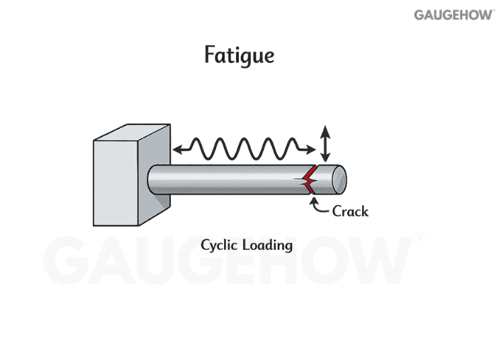
Q11. What is fatigue failure, e and why is it the default risk in rotating parts?
Fatigue is failure from repeated stress cycles, often below yield. Shafts, gears, and springs see alternating stresses, so crack initiation and growth become the true limit.
Q12. What is the endurance limit?
It is the stress amplitude a material can withstand for very large cycle counts under defined conditions.
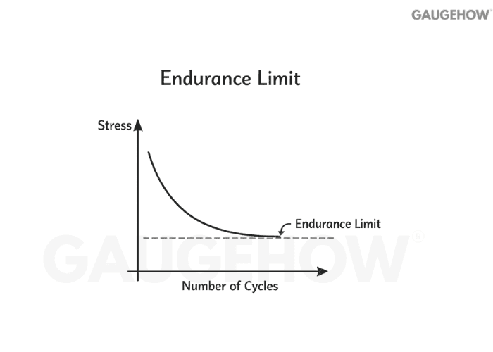
Many steels show practical endurance-limit behaviour, while many nonferrous alloys do not show a sharp plateau.
Q13. What is an S–N curve, and what does the knee mean?
It plots stress amplitude versus cycles to failure. The knee marks the transition from steep finite-life behaviour to the flatter long-life region.
Q14. Define mean stress and alternating stress with a tiny example.

Q15. Modified Goodman vs Soderberg vs Gerber: what changes?
Goodman uses ultimate strength as the mean-stress intercept, Soderberg uses yield strength, and Gerber uses a parabola. In practice, Soderberg is most conservative, Goodman is common, and Gerber is used when supporting data exists.
Q16. What is notch sensitivity, and why is Kf not equal to Kt?
Kt is geometric elastic concentration. Kf reflects fatigue behaviour and includes notch sensitivity. A common link is
where (q) depends on the material and notch radius.
Q17. How do you estimate a corrected endurance limit quickly?
Start with a baseline endurance value, then reduce it using factors for surface finish, size, reliability, temperature, and loading type. The corrected value is what you compare your alternating stress against, not the optimistic lab-specimen value.
Q18. How do you improve fatigue life without changing the material?
Reduce stress concentration, improve surface finish at critical sections, introduce compressive residual stress where possible, and reduce misalignment and mean stress. These changes often outperform a simple strength upgrade because fatigue starts locally.
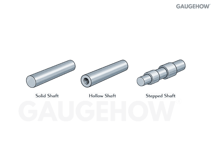
Q19. What is a shaft?
A shaft is a rotating element that transmits torque and supports components like gears and pulleys. Most real shafts see torsion plus bending plus fatigue, not torsion alone.
Q20. What is a drive shaft, and what loads does it see?
A drive shaft transmits power between locations and typically sees torque, bending from misalignment, dynamic loads from speed changes, and sometimes axial thrust, depending on the system.
Q21. How do you size a solid shaft for torque only?
Use the Torsion formula explanation.
Micro example: 200 N·m torque with allowable shear 40 MPa gives a diameter close to 30 mm, after consistent unit conversion.
Q22. How do you design a shaft for combined bending and torsion?
Most failures happen because bending and torsion are treated separately, so follow a consistent sequence.
• Find the critical section, usually at a shoulder, keyway, or gear seat.
• Compute bending moment and torque at that section from the load path.
• Convert to stresses, then apply fatigue concentration factors where notches exist.
• Combine stresses using the failure theory you are using for the material, then size and re-check stiffness and deflection.
That method prevents “safe-by-torque” shafts that crack at geometry transitions.
Q23. Why do shafts crack near shoulders and keyways?
Those features amplify local stress, and they sit on the surface where cracks initiate. Poor radii, rough machining marks, fretting, and misalignment raise the alternating stress even further.
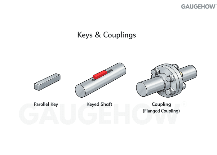
Q24. Key vs spline: when do you use which?
Keys are simple and economical for moderate torque and straightforward assembly. Splines distribute load over multiple teeth, handle higher torque, and support sliding hubs, but demand tighter manufacturing control.
Q25. How do you size a rectangular sunk key?
Check shear and bearing. For shear, a common estimate is tau ≈ 2T/(dbl).
Example: (T = 300) N·m, (d = 40) mm, (b = 12) mm, allowable shear 50 MPa gives a key length near 25 mm, then verify bearing stress.
Q26. What are rigid and flexible couplings, and where do each fit?
Rigid couplings suit well-aligned shafts and give high torsional stiffness. Flexible couplings tolerate misalignment and absorb shock, which is why they are common in real installations.
Q27. How do you select a coupling for misalignment and shock?
Apply the service factor to the torque first, then match the coupling type to the misalignment and damping needs. After that, check speed rating, environmental compatibility, and installation constraints.
Q28. What are the types of fits in machine design?
Clearance fits assemble easily and allow motion, transition fits can assemble with small clearance or light interference, and interference fits lock parts to prevent relative movement under load.
Q29. What does a G5 tolerance mean on a shaft?
The letter sets the shaft tolerance zone position relative to nominal, and the number sets the IT grade width. A G5 shaft typically lies below nominal with a tight band, so it tends to produce small clearance with common hole-based selections. Always confirm limits from ISO tables for your nominal size.
Q30. How do you choose fits for bearing seats and hubs?
Decide based on whether a ring tends to creep relative to its seat under load direction. Use interference where the ring would otherwise creep, and avoid excessive interference where housing distortion or thermal growth would reduce bearing life.
Q31. What is an interference fit, and how do you estimate assembly feasibility?
Interference means the shaft is slightly larger than the hole, so assembly needs pressing or thermal help.
Quick check:
Heating a 50 mm steel hub by 80°C expands it by about 0.048 mm, which can overcome typical small interferences.
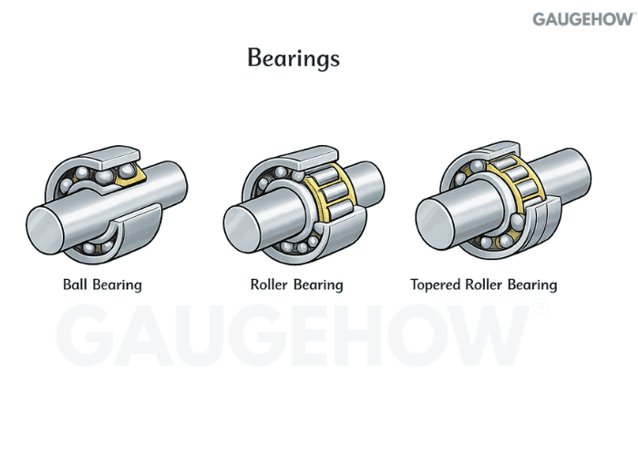
Q32. Rolling vs sliding bearings: how do you decide?
Rolling bearings give low friction and a predictable rating life. Sliding bearings handle shock, contamination tolerance, and very high speed well, but require stronger lubrication and heat control.
Q33. What is L10 bearing life, and how do you calculate it?

Q34. How do you pick bearing type for radial and axial loads?
Deep groove ball bearings suit radial plus moderate axial loads. Angular contact suits higher axial load, tapered roller suits combined loads robustly, and spherical roller suits heavy radial loads with misalignment tolerance.
Q35. What are common bearing failure modes and quick prevention actions?
Bearing failures are usually system failures, not catalogue failures.
• Keep contamination out with sealing and clean handling.
• Control alignment and runout so edge loading does not occur.
• Match fits to load direction and operating temperature so creep and distortion are avoided.
• Choose lubricant viscosity for operating temperature, not room temperature.
Those four controls eliminate most repeat failures without changing bearing series.
Q36. What are the module, pitch, and pressure angle?
Module sets tooth size through pitch diameter and teeth count. Pressure angle affects load components and influences strength, noise, and bearing reaction forces.
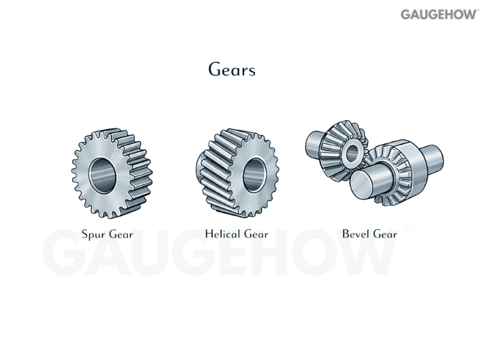
Q37. Spur vs helical vs bevel vs worm: what is the selection logic?
Spur is simple and efficient, but noisier at higher speeds. Helical runs smoother and carries more load per size,e but generates axial thrust. Bevel handles intersecting shafts, while a worm gives a large reduction in compact packaging with efficiency trade-offs.
Q38. How do gears fail, and what do you check first?
Separate bending fatigue at the tooth root from contact fatigue on the flank, then evaluate scuffing risk from lubrication breakdown. Alignment and housing stiffness matter because they concentrate contact and accelerate pitting.
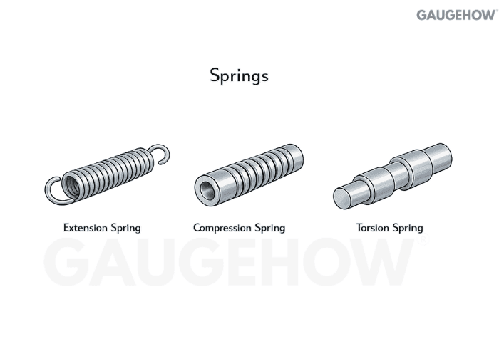
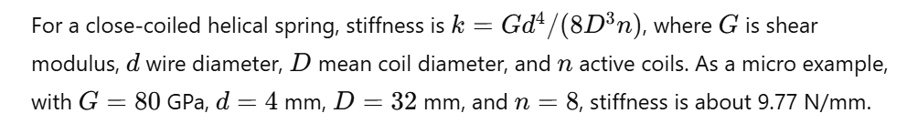
Q39. How do you calculate helical spring rate?
Q40. What checks prevent spring set and fatigue failure in service?
Check maximum shear stress with curvature correction, keep deflection away from solid height, evaluate buckling risk in compression, and control surface condition where cracks initiate.
Conclusion
Machine design questions are easy to answer poorly because the definitions are familiar, and the failure modes are not.
If you can explain where stress actually peaks, why fatigue dominates rotating parts, how Kt becomes Kf, and how fits decide whether parts creep or stay locked, you will sound like someone who designs for service, not just for calculation.
Use these 40 Q&As as a design-thinking checklist: keep the answer short, tie it to a failure mode, and add a micro example only when it clarifies a real sizing decision.


