Mechanical Engineering Technical Interview Questions


Deepak S Choudhary
Learn More in This Video
Subscribe to GaugeHow for More
Torque, RPM, power, efficiency, loads, safety factor, reliability, and maintenance show up in almost every mechanical interview. This rapid Q&A gives you short, engineer-sounding answers that connect definitions to real decisions, like sizing a shaft, tightening a joint, choosing a margin, or preventing repeat failures.
In basic mechanical terms, you manage forces, motion, and energy flow. You also explain choices using units, margins, and failure logic.
Have you ever known the topic, but still felt slow when someone asked, “So what does that actually mean in a machine?”
This guide covers torque, torque wrench use, torque converters, RPM meaning and idle RPM fluctuation, efficiency basics, load classifications, static versus dynamic loading, safety factor thinking, reliability, maintenance types, and common failure modes.
Q1. Torque: What are you actually measuring when you say “torque”?
Torque has units of N·m and tells you the twisting demand around a shaft or fastener axis. In machines, it is the “twist load” that creates torsional stress or joint slip risk. The design relevance is whether the part can carry that twist without yielding, cracking, or loosening.
Q2. How is torque different from force?
Force is a push or pull. Torque is the force that a force produces about an axis when it acts with a lever arm. The same force can create very different torques depending on the perpendicular distance to the axis.
Q3. Why does the lever arm length change the torque so much?
Torque grows with the perpendicular distance to the axis because that distance creates a rotational tendency. That is why a longer wrench feels easier for the same tightening goal. In design terms, geometry can amplify or reduce the moment a component “feels.”
Q4. How do you compute torque from a simple setup?
You multiply the applied force by the perpendicular lever arm distance.
Micro example: if you apply 50 N at a 0.2 m radius, the torque is 10 N·m.
The interview-safe detail is “perpendicular distance,” not the visible length.
Q5. Why does a gearbox increase torque but reduce speed?
A gearbox trades rotational speed for turning capacity. Ignoring losses, power stays about the same, so raising torque usually means lowering RPM. In the real world, efficiency losses reduce the delivered output.
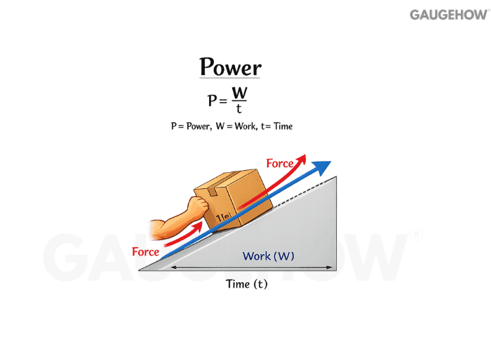
Q6. Torque vs power: how should you explain the difference quickly?
Torque tells you how strongly the system can twist. Power tells you how fast it can deliver energy. You can have high torque at low speed or lower torque at high speed and still deliver similar power.
Q7. How do engineers measure torque in practice?
You either measure shaft strain linked to torsion or infer torque from force and geometry in a controlled setup. In testing, instrumentation is preferred because it reports what the shaft actually carries. In assembly, tools control the applied twisting input, but the clamp load still depends on the friction scatter.
Q8. Torque wrench: what does the “click” mean, and what should you do next?
The click means the tool has reached its set torque and is signaling you to stop applying more turning moment. Release and reset your hand position rather than “pulling through” the click. This matters because extra motion after the click can overshoot torque and increase scatter.
Q9. What does RPM mean in rotating equipment?
RPM is revolutions per minute, a direct measure of rotational speed. It is not a force, and it is not a torque.
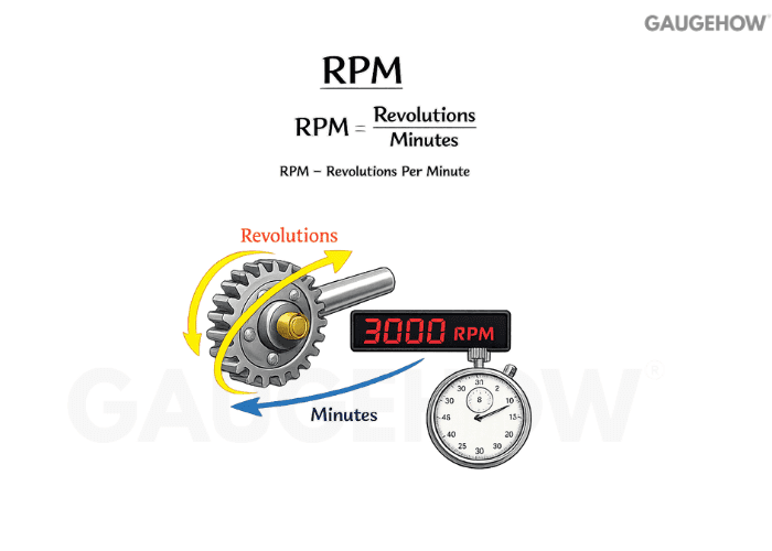
RPM matters because it drives power, heating, vibration behavior, and how many fatigue cycles a rotating part accumulates over time.
Q10. How do you connect torque, RPM, and power in a way an interviewer trusts?
Power equals torque multiplied by angular speed. A practical conversion is:
Power (kW) = Torque (N·m) × RPM / 9550.
Worked example: Suppose a motor delivers 60 N·m at 1500 RPM.
Power (kW) = 60 × 1500 / 9550 ≈ 9.42 kW.
If the same system runs at higher RPM with lower torque, power can stay similar, so speed and torque must be discussed together.
Torque–RPM–Power Quick Conversion Card
What you have | What you want | Quick relation (common units) |
Torque + RPM | Power | Power (kW) = Torque (N·m) × RPM / 9550 |
Power + RPM | Torque | Torque (N·m) = Power (kW) × 9550 / RPM |
Power + Torque | RPM | RPM = Power (kW) × 9550 / Torque (N·m) |
SI reminder | Units | 1 kW = 1000 W, torque in N·m, RPM in rev/min |
Q11. Why can a high-speed motor feel “weak” even if it is powerful?
At high speed, torque may be low, so it cannot overcome high starting loads without gearing. Power is there, but it is delivered through speed. That is why reducers exist: they convert high-speed, low-torque output into low-speed, higher-torque output.
Q12. What happens to torque and speed across a drive train with losses?
Each stage adds losses through friction, churning, and deformation. Those losses reduce delivered power, which then limits the output torque you can get at a given speed. That is why an efficiency estimate is needed when you size the last component in the chain.
Q13. Why does idle RPM go up and down while parked?
Idle fluctuation is usually the control system adjusting the torque to keep the engine stable under changing conditions. Loads like the A/C compressor, alternator demand, power steering, or cooling fan can switch on and off, and the controller compensates. Temperature changes, sensor drift, or small air and fuel disturbances can also cause “hunting.”
Q14. Torque converter: what problem does it solve, in simple terms?
A torque converter is a fluid coupling that transfers torque while allowing controlled slip between the input and output. It helps smooth engagement and can multiply torque when the output speed is low. As speeds come closer, it behaves more like a coupling to reduce slip.
Q15. If two motors have the same power rating, why do they feel different in use?
Their torque-speed curves can be very different. One may deliver strong low-speed turning capacity, which feels “pulling,” while another may need RPM to build capability. The right choice depends on starting torque, steady running load, and operating speed.
Q16. What is efficiency in mechanical terms?
Efficiency is the fraction of input power that becomes useful output power.
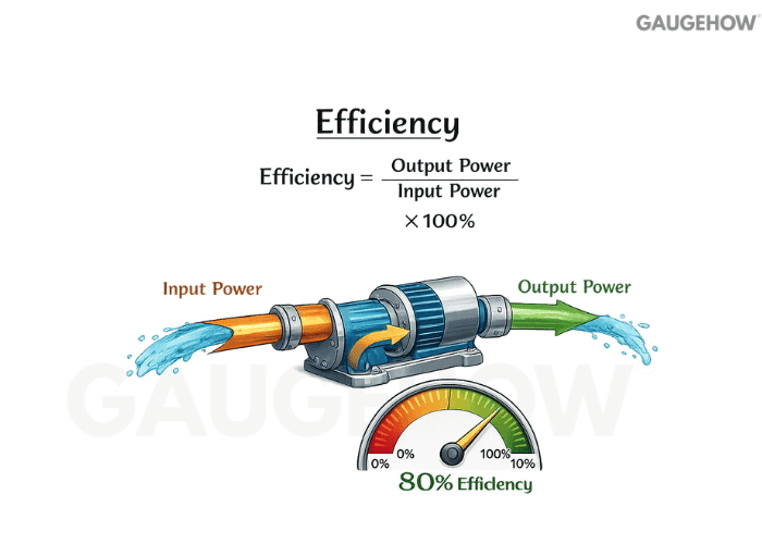
Whatever does not show up at the output turns into heat, noise, leakage, or drag losses. It matters because losses raise temperature, reduce delivered performance, and shorten component life.
Q17. Why do we talk about different kinds of efficiency?
Different losses dominate in different systems. Mechanical losses come from friction and drag, volumetric losses come from leakage or slip, and electrical losses come from resistive heating. Separating them helps you diagnose where performance is going.
Q18. How do you compute efficiency with a tiny numeric check?
You divide output by input using the same power basis.
Micro example: if input is 5 kW and output is 4 kW, efficiency is 0.8, or 80%.
This quick check is useful when you sanity-check a test result or a rating plate claim.
Q19. Why does efficiency often drop at very light loads?
Fixed losses do not scale down much with load. Bearing drag, seal friction, and churning can stay relatively similar, so useful output becomes a smaller fraction of input. That is why right-sizing equipment matters in real plants.
Q20. What are common engineering moves that improve efficiency?
Start with alignment, lubrication quality, and eliminating avoidable friction sources. Then look at correct sizing so the machine runs in a healthier operating window. Finally, reduce unnecessary slip and leakage because those losses often turn straight into heat.
Q21. Load classification: what types of loads should you name confidently?
In interviews, name loads by how they stress the part: axial, bending, torsion, and shear.
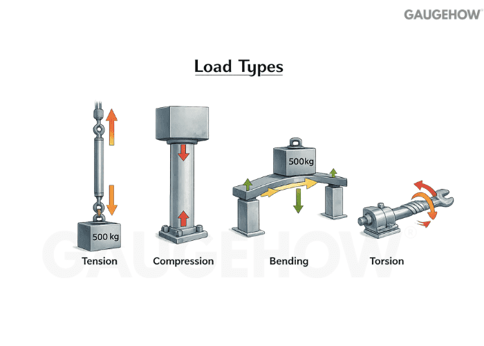
Real components often see combined loading, which is where stress state and failure risk rise. The clean habit is to connect the load type to the likely failure mode.
Load Type → Dominant Failure Mode Matrix

Load type (dominant) | Typical “first failure” risk | Why does it happen first |
Axial tension | Necking/yield or fracture | Uniform stress until the material limit is reached |
Axial compression | Buckling (slender members) | Instability can occur before the strength limit |
Bending | Fatigue crack at the surface/notch | The highest tensile stress sits at the outer fiber |
Torsion | Shear yielding or torsional fatigue | Max shear stress builds at the surface |
Shear (direct) | Shear yielding / joint slip | Contact planes slide if capacity is exceeded |
Shock/impact | Brittle fracture or notch crack | High peak stress and fast rise time |
Q22. What is a static load from a design viewpoint?
Static loading means stress changes slowly enough that inertia effects are negligible. The main concern becomes peak stress versus allowable strength, along with deflection limits. Static cases can still fail if stress concentrations or assembly errors amplify local stress.
Q23. What makes a load dynamic in mechanical design?
Dynamic loading means the stress varies with time, so inertia, vibration, and resonance can amplify the effective stress beyond the average load. Fatigue becomes a major concern because cycles accumulate damage. Even small repeating stress ranges can matter if the cycle count is high.
Q24. How do you identify static vs dynamic load on a real machine?
Ask whether the part sees a time-varying stress history.
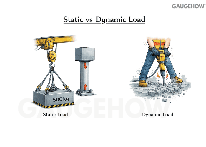
A steady suspended weight is mainly constant stress, while rotating, reciprocating, or impact-driven systems create changing stress over time. Once stress repeats or reverses, fatigue thinking usually enters.
Q25. Impact load vs cyclic load: what’s the clean distinction?
Impact is a short-duration event with a very high peak force and a fast rise time. Cyclic loading repeats over time, even if the peak is lower. Both can be damaging, but they drive different design margins and inspection priorities.
Q26. Why can a part fail in fatigue even if the peak stress seems “safe”?
Fatigue is damage growth from repeated stress cycles, not a single overload event. Cracks often start at notches, surface defects, or poor finishes, then extend a little with each cycle. That is why geometry, surface condition, and stress range can dominate life.
Q27. What do engineers mean by duty class or service severity?
It describes how harsh the load history is, not just how big one load is. Duty considers starts, stops, overload frequency, shock events, and operating hours. Two machines with the same peak load can have totally different life outcomes based on duty.
Q28. Service factor vs safety factor: how are they different?
Service factor adjusts the expected demand for real operating severity, like shocks and starts. The safety factor is the margin between expected demand and allowable capacity. Service factor shapes the load you design for, while safety factor protects against uncertainty around that load.
Q29. What is a safety factor, and what is it really protecting you from?
A safety factor is a deliberate margin between expected demand and allowable capacity.
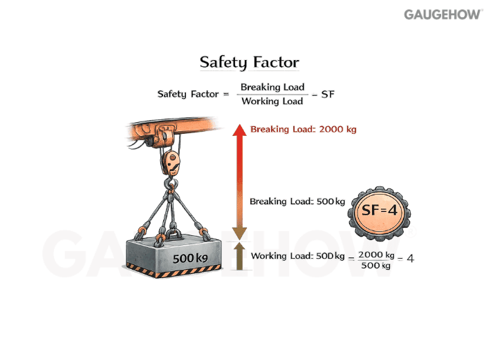
It protects you from uncertainty in loads, material strength scatter, manufacturing variation, and real-world misuse. The goal is controlled risk, not just “bigger is safer.”
Unknown peak load or misuse conditions
Material scatter and heat-treatment variation
Stress concentration and surface condition effects
Assembly and friction variation in joints
Explaining it this way shows judgment instead of a random multiplier.
Q30. How does safety factor thinking change for ductile vs brittle behavior?
Ductile parts often give warning through yielding and deformation, so you typically guard against yield and excessive deflection. Brittle behavior can fail suddenly, so flaw sensitivity and fracture risk dominate. The failure mode decides what “allowable” should mean.
Q31. Why is the safety factor for fatigue not the same as the safety factor for static strength?
Static strength compares one peak event to an allowable limit. Fatigue compares a stress range and mean stress history to endurance capability over cycles. A design that is static-safe can still be fatigue-unsafe if cycling is severe.
Q32. What is a common safety factor mistake in real engineering work?
Inflating the margin to hide uncertainty instead of reducing uncertainty at the source. That can make parts heavier and costlier while still missing the real driver, like a sharp notch or misalignment that spikes stress. A better practice is to identify the dominant uncertainty and control it.
Q33. How do you choose the right maintenance strategy for a machine?
Start from what fails, how it fails, and what it costs when it fails. Then match the strategy to detectability, downtime impact, and how predictable degradation is.
Use scheduled work when wear-out is time-based and predictable
Use condition-based methods when failure gives a measurable warning
Use run-to-failure when consequences are low, and replacement is easy
Use corrective actions with root-cause focus when repeats are happening
Use redesign or protection when the failure mode is structural or systemic
This framing shows you see maintenance as a reliability control loop, not a calendar.
Q34. What are the main maintenance types, and when do you use each?
Preventive maintenance is planned by time or usage to reduce failure probability.
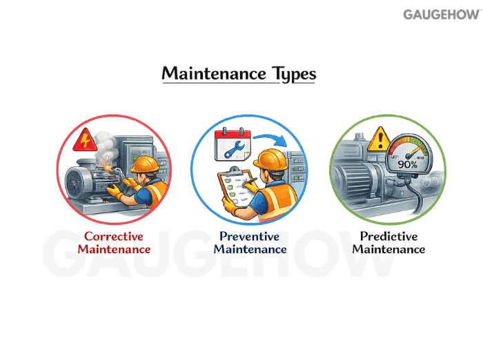
Predictive maintenance uses condition signals to intervene when degradation is detected. Corrective maintenance restores function after a fault, and breakdown maintenance is the end,d where you only act after failure.
Q35. What is the difference between reliability and maintainability?
Reliability is how likely a system is to run without failing over time and under certain conditions.
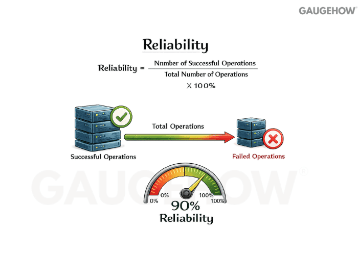
Maintainability is how quickly and consistently you can restore it after failure. Availability links both and is often summarized through MTBF and MTTR.
Q36. Which condition-monitoring signals are most useful in mechanical systems?
Vibration changes can indicate imbalance, misalignment, looseness, or bearing damage. Temperature rise often signals friction, lubrication issues, or overload. Lubricant condition and debris can reveal wear long before catastrophic failure.
Q37. Why do “fixed fast” repairs sometimes lead to repeat downtime?
Because the symptom gets removed, not the cause. Misalignment, contamination, poor lubrication practice, and incorrect assembly torque can recreate the same damage. Strong answers show you think in cause chains and feedback loops.
Q38. Fatigue failure: what would you expect to see on the part?
Fatigue usually shows a crack that initiated at a notch or surface defect, grew over time, and then ended in a final rapid fracture region. You often see evidence that the part carried a load for many cycles before the final break. The key point is that fatigue is a growth process, not a single moment.
Q39. Wear failure: what are the usual mechanical drivers?
Wear rises when lubrication is wrong, alignment is off, surfaces are rough, or contamination enters the contact. Once clearances change, load distribution shifts and damage accelerate. Many wear failures are actually system failures in sealing, cleanliness, and lubrication control.
Q40. Corrosion, creep, and thermal effects: how do you explain them simply?
Corrosion removes material and creates pits that behave like notches. Creep is time-dependent deformation under sustained load at elevated temperature. Thermal cycling can create expansion-mismatch stresses that initiate cracks, especially near sharp geometry changes.
Conclusion
If you link the definition to the decision, you sound like an engineer, not a memorizer. Keep answers anchored to units, load paths, uncertainty, and failure mode. With that habit, even “basic” topics like torque, RPM, and maintenance come across as confident and credible.


