
Common Strength of Materials (SOM) Interview Questions


Deepak S Choudhary
Learn More in This Video
Subscribe to GaugeHow for More
Strength of Materials explains how solids resist load through Stress and Strain, and how that leads to elastic deformation, plastic deformation, and failure. This guide covers Stress-Strain Curve, Hooke’s Law, Young’s Modulus, Poisson’s Ratio, Shear Stress, Bending Stress, Torsion, and Factor of Safety. It finishes with a clean Q&A set plus exam-aligned practice.
Strength of Materials studies how a loaded part develops stress and strain, how it deforms, and where it fails. It turns force and geometry into stiffness, strength limits, and safe design margins.
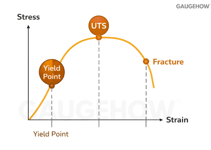
Have you ever computed stress, seen a safe number, and still felt unsure because yield, UTS, and fracture seem interchangeable? That confusion is common because the Stress-Strain Curve has multiple limits, and each one answers a different design question.
This guide is a tight Q&A bank covering stress and strain, Hooke’s law, Young’s modulus, Poisson’s ratio, the stress-strain curve, shear, bending, torsion, and factor of safety, plus exam-aligned questions and one high-intent MCQ.
Stress And Strain
1) What is stress, in one line?
Stress is internal resistance per unit area developed inside a loaded body.
2) What is strain, and why is it dimensionless?
Strain is deformation divided by original dimension, so units cancel and comparisons stay consistent across part sizes.
• Axial strain captures length change along the load path.
• Shear strain captures angular distortion between layers.
• Volumetric strain captures net volume change under pressure.
Once you know which strain matters, the right stiffness constant and limit become clear.
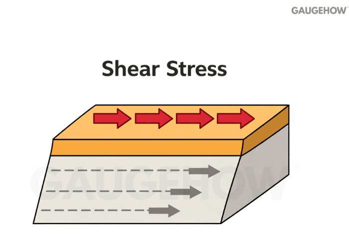
3) What is normal stress vs shear stress?
Normal stress acts perpendicular to the section and changes length. Shear stress acts parallel to the section and drives sliding.
4) What is axial (direct) stress?
Axial stress is caused by a tensile or compressive force acting through the centroidal axis, so the section is mainly in uniform tension or compression.
5) Stress vs pressure: are they the same?
Pressure is an external load intensity applied by a fluid. Stress is the internal response within the solid.
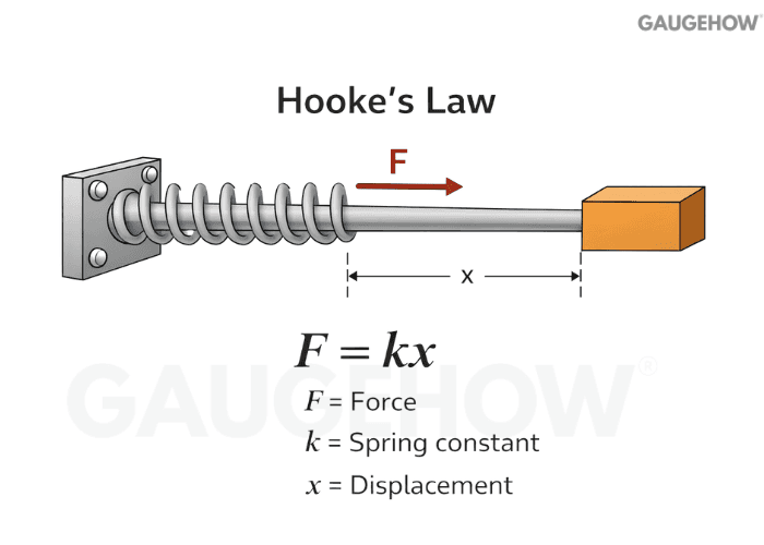
6) What is Hooke’s law, and where does it apply?
Hooke’s law says stress is proportional to strain only in the linear elastic region. Once the curve stops being linear, Hooke’s law is no longer valid.
7) Hooke’s law is valid up to which point on the stress-strain curve? (MCQ)
A) Fracture point
B) Yield point
C) Proportional limit (linear region)
D) Ultimate tensile strength
Answer: C. Hooke’s law is a linear relation, so it ends when proportionality ends, even if the material may still be “mostly elastic” for a short range.
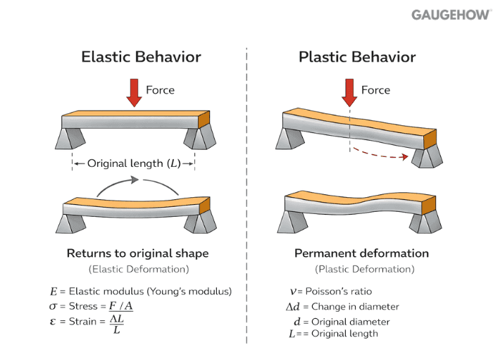
8) Elastic deformation vs plastic deformation: what is the real difference?
Elastic deformation is fully recoverable after unloading. Plastic deformation leaves a permanent set, even after load removal.
9) What is engineering stress vs true stress?
Engineering stress uses the original area. True stress uses instantaneous area, so the difference matters after large plastic strain and necking.
10) What is the simplest way to avoid unit mistakes in stress problems?
Use one consistent unit system end to end, and add a fast material-property sanity check when values come from different sources.
For isotropic linear elasticity, E = 2G(1 + ν), so if E = 200 GPa and ν = 0.30, then G = 200 / (2(1 + 0.30)) = 76.9 GPa.
If your G is nowhere near that, you likely mixed units or copied an incompatible set of constants. This quick check catches inconsistent inputs before they turn into clean-looking but wrong results.
Stress-Strain Curve Landmarks: What Controls Design
Landmark | What It Means | What It Controls | Typical Design Choice |
Proportional Limit | End of linear stress–strain | Linear stiffness assumptions | Use E for small-deflection checks |
Yield / 0.2% Proof | Permanent set begins | Function and fit risk | Keep working stress below the yield-based allowable |
UTS | Peak engineering stress | Peak load capacity | Use cautiously for ultimate-capacity cases |
Fracture | Separation occurs | Final failure | Crack/notch sensitivity dominates decisions |
Stress-Strain Curve, Yield, UTS, And Fracture
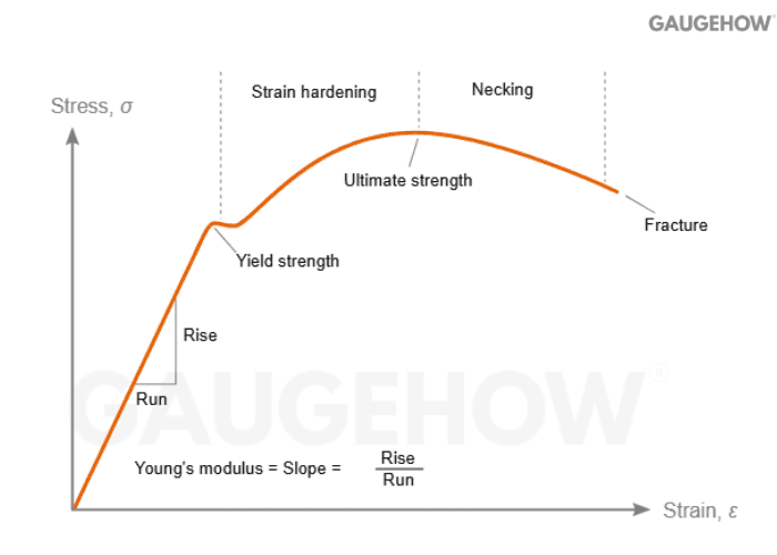
11) What does the stress-strain curve actually tell you?
It shows stiffness, the start of plasticity, peak load capacity, and how the material fails, all in one plot.
12) What is the proportional limit vs the elastic limit?
Proportional limit is where linearity ends. The elastic limit is where permanent strain begins. They are close, but not identical, in all materials.
13) What is yield strength, and why is it a design anchor?
Yield strength is the stress at which permanent deformation starts. Many parts “fail in function” at yield long before fracture, so yield is often the controlling limit. ASTM E8/E8M is a common tensile-test standard used to determine values like yield and tensile strength.
14) What is 0.2% proof stress (offset yield)?
It defines “yield” for materials without a sharp yield point by using a small permanent strain offset, so the value is measurable and repeatable.
15) What is ultimate tensile strength (UTS)?
UTS is the maximum engineering stress reached before necking reduces load capacity, but for ductile static design, the more useful limit is yield, because that is where permanent set starts.
Allowables are typically derived from yield rather than UTS for ductile static parts, so if Sy = 250 MPa and FoS = 2, then σ_allow ≈ 125 MPa.
If working stress exceeds that level, the part can remain unfractured yet still fail in function because it has taken a permanent shape change. That is why UTS is a peak-capacity marker, while yield is usually the safe-design marker.
16) Why is fracture stress not the same as UTS?
UTS is the peak on the engineering curve. Fracture occurs later, after localization, so the engineering stress at fracture can be lower.
17) Ductile vs brittle failure: what changes in your design check?
Ductile failure usually gives a warning through plastic strain, so yield-based limits are common. Brittle failure can occur with little plasticity, so crack sensitivity and stress concentrations become more dangerous.
18) Toughness vs resilience: what’s the quickest way to separate them?
Resilience is elastic energy stored and recovered. Toughness is the total energy absorbed up to fracture.
19) What is necking, and why should you care?
Necking is localized thinning, which is where “uniform strain” ends and the cross-section starts losing area fast.
• It shifts the specimen from uniform deformation to localization.
• It makes true stress more relevant than engineering stress after UTS.
• It explains why the curve can drop while damage is still accelerating.
If you ignore necking, you can misread both capacity and failure location.
20) Which property should control design: yield, UTS, or fracture?
It depends on what “failure” means for the part.
Design Situation | What Usually Controls | What You Compare Against | Why It Matters |
Fit or alignment must remain | Yield strength | Max working stress | Permanent set breaks the function |
Ultimate load capacity matters | UTS (carefully) | Peak stress capacity | Margin to collapse |
Crack or notch risk is high | Fracture behavior | Crack growth or toughness-based logic | Brittle failure can be sudden |
Deflection is the problem | Elastic modulus (E) | Deflection limit | Stiffness drives usability |
Elastic Constants (Young’s Modulus, Poisson’s Ratio)
21) What is Young’s modulus (E), in one line?
E is the slope of the straight-line elastic portion of the stress-strain curve.

22) How is E actually defined during testing?
Young’s modulus is the slope of the straight, linear part of the stress–strain curve, so it tells you stiffness before yielding starts.
23) What is Poisson’s ratio (ν)?
Poisson’s ratio links axial strain to lateral strain under uniaxial loading. If a bar stretches, ν tells you how much it thins sideways.
24) What is shear modulus (G), and where does it matter most?
G links shear stress to shear strain in elasticity. It strongly controls shaft twist and shear deformation response.
25) What is bulk modulus (K)?
Bulk modulus K links pressure to volumetric strain, but it is not what you use to size a beam in bending.
For bending, the Bending Equation relation σ = My/I is the standard sizing backbone, so you compute M at the critical section, take y at the extreme fiber, and use the correct section I about the neutral axis.
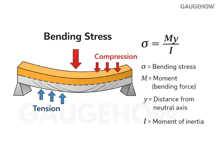
For a rectangle, I = bd³/12, so a small increase in depth gives a large stiffness and stress benefit for the same moment.
• M comes from the critical-section bending moment
• y is the distance to the outer fiber
• I is the second moment of area.
That depth leverage is why bending failures often disappear with smarter section geometry rather than thicker material everywhere.
26) How are E, G, K, and ν related for isotropic materials?
These constants are not independent. If you pick inconsistent values, your deformation predictions will be wrong even if the stresses look fine.
27) What are typical elastic property values engineers use for quick stiffness estimates?
In routine structural calculations, steel’s elastic modulus is typically taken as 29,000 ksi (about 200 GPa), and AISC reliability work uses a nominal 29,000 ksi while documenting the variability around that value.
As a concrete grade example, A36 is often summarized with E ≈ 200 GPa and Fy ≈ 250 MPa, which is enough for quick stiffness and yield-margin checks before you lock the project spec.
For 6061 aluminum, common datasheets list E ≈ 68.9 GPa (10,000 ksi), so deflection typically rises by about 3× versus steel at the same geometry.
Bending And Torsion
28) What is shear stress in beams, conceptually?
Shear stress in a beam section comes fromthe transverse shear force and is not uniform across the depth.
29) What is the bending stress equation most people use?
A common Bending Equation relation is σ = My/I, linking bending moment, section geometry, and distance from the neutral axis.
30) Where is the bending stress maximum in a typical beam section?
Bending stress is maximum at the extreme fibers, farthest from the neutral axis, because stress scales with distance from that axis.
In shafts under torque, the Torsion Equation checks use τ_max = Tr/J and θ = TL/(GJ), with τ_max occurring at the surface where r is largest, which is why surface quality and features matter. Increasing the diameter boosts J strongly, so both torsional stress and twist drop quickly, even with a small geometry change.
• τ_max occurs at the surface • θ falls as J increases • larger diameter raises J sharply. This is why stress checks alone are not enough when twist or alignment is the functional limit.
31) What is the neutral axis?
The neutral axis is the line in a bent section where bending stress is zero, separating the tension side from the compression side.
32) What is section modulus, and why do designers love it?
Section modulus is a geometry shortcut that turns a bending moment into maximum bending stress quickly, which is why it is used for fast sizing.
33) What is the link between the Shear Force Diagram and the Bending Moment Diagram?
The relationship is dM/dx = V, meaning shear force is the rate of change of bending moment along the beam. When V = 0, M typically reaches a local maximum or minimum, and that section is a prime candidate for max bending stress.
Under a uniformly distributed load, shear varies linearly with x, so the bending moment becomes a parabola. This link is what lets you locate critical sections before you start sizing the section.
34) What is torsion in shafts?
Torsion is shaft twisting under applied torque, creating shear stress that rises from the center to the surface.
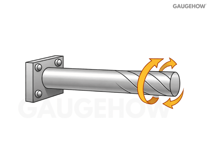
35) Where is the torsional shear stress maximum in a circular shaft?
Shear stress varies with radius as τ(r) = Tr/J, so it is τ = 0 at the center, where r = 0, and reaches its maximum at the surface,ce where r = R. That is why surfacing and stress raisers like keyways dominate torsional failures even when the average stress looks fine.
The distribution also explains why increasing the diameter is such an efficient way to reduce torsional stress. In shaft design, the surface is where you win or lose.
36) What controls the angle of twist the most in real design?
Torque level, shaft length, shear modulus, and polar geometry dominate. Long shafts twist even when the stresses look acceptable.
37) How are shear force and bending moment related in one rule?
They are linked by dM/dx = V, so shear tells you how the bending moment changes along the span. That is why moment peaks often sit where shear crosses zero.
38) What is deflection, and when does it control design?
Deflection is displacement under load, and it often controls usability and alignment before stress limits are reached. A beam can be “safe in stress” yet still fail in function due to excessive deflection.
39) What mainly governs beam deflection in simple bending problems?
Deflection is driven by span, load distribution, and stiffness terms like E and I. In many beams, increasing section depth is the fastest way to cut deflection.
40) What is strain energy in Strength of Materials?
Strain Energy is energy stored in a member due to elastic deformation under load. It becomes useful when you want deflection from energy methods instead of direct integration.
41) What triggers column buckling?
Buckling is a stability failure where a slender column bows sideways under compression before material strength is reached. Slenderness and end conditions can dominate the safe load.
Factor Of Safety
42) What is the factor of safety (FoS)?
FoS is the ratio of a chosen failure limit to the expected working condition, used to cover uncertainty and consequence.
43) How do you choose FoS without guessing?
Treat FoS like a controlled margin that matches uncertainty, consequence, and your ability to verify the inputs.
• Increase FoS when loads, constraints, or material scatter are uncertain.
• Increase FoS when the failure consequence is high, or the detection is weak.
• Reduce FoS only when testing and controls are strong.
That keeps the factor defensible in design reviews instead of being a default habit.
44) What is allowable stress vs working stress?
Allowable stress is your limit after applying FoS and design rules. Working stress is what your part actually sees under the load case.
45) What are the most common setup mistakes that make “safe” designs fail?
Most failures come from the wrong model, not the wrong equation. Using gross area instead of net area near holes or threads, ignoring eccentricity that adds bending, missing stress concentration locations like fillets or keyways, and checking only peak stress while deflection drives failure are the common traps. If you fix these four, your decisions improve fast.
Conclusion
Strength of Materials becomes simple when you lock three things early: load path, failure mode, and the property you compare against. Stress and strain tell you what the part is feeling, Hooke’s law and E tell you how much it will move, the stress-strain curve tells you where permanent deformation starts, and bending or torsion formulas tell you where the peak stress actually lives.
Use yield when shape must not change, use stiffness when deflection is the real limit, and treat FoS as a controlled response to uncertainty, not a default number.


