Engineering Mechanics
Cartesian Coordinate System Explained Simply for Engineering Mechanics
Before you can solve a single force problem, you need a way to say exactly where something is. Where is the load on a beam? Where does a rope pull? Where is the center of a wheel?
The Cartesian coordinate system is the answer. It is the map that engineers use to pin down any point in space using simple numbers.
In our last lesson we introduced Engineering Mechanics and why it matters in design. This lesson gives you the tool that every later topic depends on. By the end, you will be able to read any point, plot it yourself, tell the four quadrants apart, and measure the exact distance between two points. Let us build it from the ground up.
What Is the Cartesian Coordinate System?
The Cartesian coordinate system is a way to locate any point using numbers measured from a fixed starting point.
Think of a chessboard. To describe a square, you say something like "column C, row 4." Two numbers, and everyone knows the exact square. The Cartesian system works the same way, only smoother, because it uses smooth number lines instead of fixed boxes.
It is named after René Descartes, a French mathematician who connected geometry (shapes) with algebra (numbers). That single idea is the reason your CAD software can draw a bracket, and the reason a calculator can find a force direction.
One idea to hold on to: in this system, position is just numbers. Once position becomes numbers, we can add it, subtract it, and calculate with it. That is exactly what mechanics needs.
Why Engineers Use Cartesian Coordinates
Picture a workshop drawing of a steel plate with holes to be drilled. If the drawing just said "drill a hole somewhere near the top left," no two workers would drill in the same place.
Instead, the drawing gives each hole a location like (30, 45) in millimetres. Now every worker, every machine, and every inspection tool agrees on the exact spot.
That is the whole point. Engineers deal with forces, distances, and shapes that must be exact. Cartesian coordinates turn "roughly there" into a precise, shareable number that a person or a machine can act on.
This is also the language your design tools speak. When you type coordinates into a program like AutoCAD to place a line, you are using the Cartesian system directly.
The Axes: X, Y, and Z
An axis is a straight number line used for measuring in one direction.
The Cartesian system uses two or three axes that cross each other at right angles (90 degrees):
The x-axis runs left and right. It is the horizontal line.
The y-axis runs up and down. It is the vertical line.
The z-axis runs in and out, toward you and away from you. It is used only when we work in 3D.
An easy way to feel this: stand in the corner of a room. The line where the floor meets the wall on your right is one axis. The line where the floor meets the wall on your left is a second axis. The vertical line up the corner is the third axis. Every corner of a room is a mini 3D coordinate system.

The Origin: Where Everything Starts
The origin is the point where all the axes cross. It is your zero, your starting line.
Its coordinates are (0, 0) in 2D and (0, 0, 0) in 3D, because you have moved zero distance in every direction.
Every other point is described by how far it sits from this origin. So the origin is like the front door of a house. All directions inside are given as "so many steps from the door."
Choosing where to place the origin is a real engineering decision. Put it at the corner of a part, the base of a column, or the center of a shaft, and every measurement afterward becomes cleaner. A smart origin makes the whole calculation easier.
How to Read a Point: Coordinates and Ordered Pairs
A coordinate is a number that tells you how far a point sits along one axis.
In 2D, a point is written as an ordered pair:
P(x, y)
x is how far the point is along the x-axis (left or right).
y is how far the point is along the y-axis (up or down).
The word "ordered" matters. The point (3, 5) is not the same as (5, 3). The first number is always x, the second is always y. Swapping them puts you in a completely different spot, just like reversing a house number and a street number would send a delivery to the wrong place.
In 3D we simply add the z value:
P(x, y, z)
Here z tells you how far the point sits along the z-axis (toward you or away from you).
The Four Quadrants of the Coordinate Plane
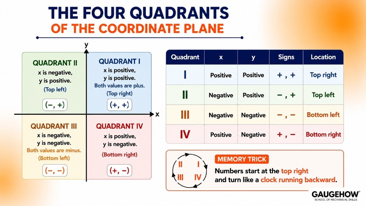
When the x-axis and y-axis cross, they split the flat 2D surface into four regions. Each region is called a quadrant.
Starting from the top right and going anticlockwise:
Quadrant I: x is positive, y is positive. Both values are plus. (Top right)
Quadrant II: x is negative, y is positive. (Top left)
Quadrant III: x is negative, y is negative. Both values are minus. (Bottom left)
Quadrant IV: x is positive, y is negative. (Bottom right)
A simple memory trick: numbers start at the top right and turn like a clock running backward.
Why should an engineer care about signs? Because in mechanics, a plus or minus is not just a number. A negative x might mean a force pushing left, and a positive y might mean it pushing up. Get the quadrant right, and your force directions come out correct.
How to Plot a Point Step by Step
Plotting means drawing a point at its correct location. Let us plot the point A(4, 3).
Start at the origin (0, 0).
Read the first number, x = 4. Move 4 units to the right along the x-axis.
Read the second number, y = 3. From there, move 3 units straight up.
Mark that spot. That is point A.
That is it. Every point is just "move sideways, then move up or down." The order never changes: x first, then y.
If a value is negative, you move the other way. For a point like B(-2, 5), you would move 2 units left and 5 units up, which lands you in Quadrant II.
2D vs 3D: When You Need the Z-Axis
Use 2D (x and y only) when everything lies flat, like a sketch on paper, a floor plan, or a single face of a part.
Use 3D (x, y, and z) when the object has depth, like a real bracket, an engine block, or a truss standing in space.
Most engineering starts in 2D because it is easier to reason about. Then, once the idea is clear, it moves into 3D for the real component. Modern modelling software such as Fusion 360 builds every solid part using x, y, and z coordinates under the hood, even when you are just clicking and dragging.
Finding the Distance Between Two Points
Often you do not just want two locations, you want the straight-line distance between them. How long is that rod? How far apart are two bolt holes?
The distance formula comes straight from the Pythagoras theorem you already know from school.
For two points in 2D, P1(x1, y1) and P2(x2, y2):
d = √[(x2 − x1)² + (y2 − y1)²]
d is the distance between the two points, in metres (m) in SI units.
x1, y1 are the coordinates of the first point.
x2, y2 are the coordinates of the second point.
In 3D, we just add the z part in the same way:
d = √[(x2 − x1)² + (y2 − y1)² + (z2 − z1)²]
Solved Mini-Example
Find the distance between A(1, 2) and B(4, 6).
Find the change in x: 4 − 1 = 3
Find the change in y: 6 − 2 = 4
Square and add: (3)² + (4)² = 9 + 16 = 25
Take the square root: √25 = 5
So the distance is d = 5 units.
Notice the classic 3, 4, 5 triangle hiding inside. The distance formula is really just Pythagoras wearing a coordinate costume.
Where Engineers Actually Use the Cartesian System
This is not just exam theory. Coordinates show up everywhere real work happens:
Free body diagrams: Force directions are split into x and y components before you can solve for equilibrium. Every force problem you will do lives on these axes.
CAD and design: Every line, hole, and curve in a drawing is stored as coordinates. This is the base skill behind engineering graphics and GD&T.
CNC machining and 3D printing: The machine head moves to exact (x, y, z) points to cut or print a part.
Structural analysis: Every joint of a truss or frame is given a coordinate so the software can calculate the forces.
Robotics and Python tools: A robot arm reaches a point by targeting its coordinates, and engineers often calculate these using Python.
Once you see it, you cannot unsee it. Coordinates are the quiet backbone of nearly every mechanical task.
Common Mistakes to Avoid
Swapping x and y. Always write and read x first, then y. (3, 5) and (5, 3) are different points.
Forgetting the sign. A missing minus sign puts your point in the wrong quadrant and flips your force direction.
Mixing up units. If x is in millimetres, y must be in millimetres too. Never mix mm and m in the same calculation.
Ignoring the z-axis in 3D. A flat answer to a 3D problem is an incomplete answer.
Frequently Asked Questions
What is the Cartesian coordinate system in simple words?
It is a system that locates any point using numbers measured from a fixed starting point called the origin. In 2D you use two numbers (x, y), and in 3D you use three (x, y, z).
Why is it called Cartesian?
It is named after René Descartes, who linked geometry and algebra so that shapes could be described using numbers.
What is the difference between 2D and 3D coordinates?
2D uses only x and y for flat shapes. 3D adds a z value for objects that have depth, like real machine parts.
How do you find the distance between two points?
Use the distance formula, which is based on the Pythagoras theorem: d = √[(x2 − x1)² + (y2 − y1)²] for 2D points.
Where is the Cartesian coordinate system used in engineering?
In free body diagrams, CAD drawings, CNC machining, 3D printing, structural analysis, and robotics. Almost every mechanics and design task uses it.
Key Takeaways
The Cartesian coordinate system locates any point using numbers from a fixed origin.
The x-axis is horizontal, the y-axis is vertical, and the z-axis adds depth for 3D.
The origin is the (0, 0) or (0, 0, 0) starting point where all axes cross.
A 2D point is written P(x, y); a 3D point is written P(x, y, z). Order always matters.
The plane splits into four quadrants, and signs decide which quadrant a point falls in.
Distance between two points comes from the Pythagoras theorem.
Coordinates power free body diagrams, CAD, CNC, and robotics.
Quick Revision Box
2D point: P(x, y)
3D point: P(x, y, z)
Origin: (0, 0) in 2D, (0, 0, 0) in 3D
Distance (2D): d = √[(x2 − x1)² + (y2 − y1)²]
Distance (3D): d = √[(x2 − x1)² + (y2 − y1)² + (z2 − z1)²]
Practice Corner
In which quadrant does the point (-3, -7) lie?
Plot the point (5, -2) in words: which way and how far do you move from the origin?
Write the coordinates of the origin in a 3D system.
Find the distance between the points (0, 0) and (6, 8).
True or false: (2, 9) and (9, 2) are the same point.
<details> <summary>Answers</summary>
Quadrant III (both x and y are negative).
Move 5 units right along the x-axis, then 2 units down along the y-axis.
(0, 0, 0).
d = √[(6 − 0)² + (8 − 0)²] = √[36 + 64] = √100 = 10 units.
False. The order of the numbers is different, so they are different points.
Conclusion
The Cartesian coordinate system is the map underneath all of Engineering Mechanics. Master reading points, plotting them, telling the quadrants apart, and measuring distances, and every force and structure problem ahead becomes far easier to handle.
Ready to build the full toolkit? Explore the Mechanical Engineer learning hub at GaugeHow, and sharpen these basics with the practice tests before you move on.
What's Next
Next up: Vectors, where we turn these coordinates into arrows that carry both size and direction, the exact tool you need to describe a force.
Internal links:
Cartesian coordinates in AutoCAD → https://gaugehow.com/course/autocad-2023
3D modelling in Fusion 360 → https://gaugehow.com/course/fusion-360
Python for Mechanical Engineers → https://gaugehow.com/course/python-for-mechanical-engineers-robotics
Engineering Graphics and GD&T → https://gaugehow.com/course/gd-t-geometric-dimension-and-tolerancing
Mechanical Engineer Hub → https://gaugehow.com/mech