Engineering Mechanics
Components of Force
Every force you meet in engineering is pulling or pushing in some direction. The problem is that directions are messy. A rope pulls a crate at 30 degrees. A wind load hits a signboard at an odd angle. A bicycle pedal force points somewhere between forward and down.
The resolution and composition of forces is the one trick that makes all of that manageable. Break every slanted force into straight horizontal and vertical pieces, solve, then put the pieces back together.
By the end of this guide you will be able to split any force into its components, add several forces into a single resultant force, and use the triangle, parallelogram and polygon laws with confidence. You only need to know what a force is and how it is represented by magnitude, direction and point of application. Everything else is built here from scratch.
What Are Components of Force?
A component of a force is one part of that force acting along a chosen direction.
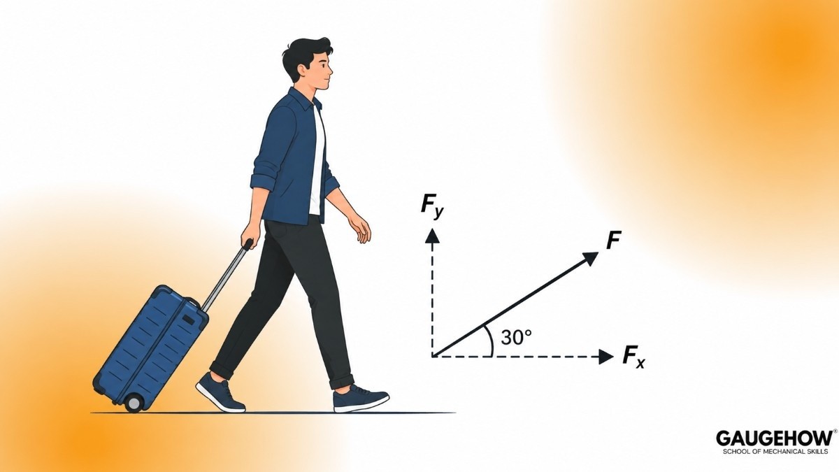
Think of pulling a suitcase with a handle. You pull along the handle, at an angle. But the suitcase only moves forward, and part of your effort is wasted lifting it slightly upward. That forward part and that upward part are the two components of your pull.
The force itself did not change. You just described it in a smarter way, as two simple pieces instead of one awkward slanted arrow.
Resolution of a force means splitting one force into components. Composition of forces means the reverse, combining many forces into one.
Both ideas are two sides of the same coin, and this whole topic lives between them.
Why engineers do this
A beam only cares about the vertical load pressing on it, not the slanted rope pulling it.
A bolt fails in one direction at a time, so you need the force along that direction.
Adding slanted arrows by eye is guesswork. Adding numbers along x and y is exact.
Rectangular Components of a Force
Rectangular components are components taken along two directions that are at 90 degrees to each other, usually the horizontal x axis and the vertical y axis.
Picture a ladder leaning against a wall. The floor is your x direction, the wall is your y direction. They meet at a right angle, and that right angle is what makes the maths easy.
The formulas
For a force F acting at angle θ measured from the positive x axis:
Fx = F cos θ Fy = F sin θ
Where:
F is the magnitude of the force, in newtons (N)
θ (theta) is the angle the force makes with the x axis, in degrees
Fx is the horizontal component, in newtons (N)
Fy is the vertical component, in newtons (N)
And to go back the other way:
F = √(Fx² + Fy²) tan θ = Fy / Fx
One simple memory aid: the component that hugs the angle uses cosine, the component across from the angle uses sine.
Solved mini example
A force of 100 N acts at 30 degrees above the horizontal. Find its components.
Fx = 100 × cos 30° = 100 × 0.866 = 86.6 N
Fy = 100 × sin 30° = 100 × 0.5 = 50 N
Check: √(86.6² + 50²) = √(7500 + 2500) = √10000 = 100 N. Correct.
So a 100 N slanted pull is exactly the same as an 86.6 N horizontal pull plus a 50 N vertical pull, applied together.
Signs matter
Components carry direction through their sign:
Right is positive x, left is negative x
Up is positive y, down is negative y
If a force points up and to the left, Fx is negative and Fy is positive. Getting a sign wrong is the single most common mistake in this topic, so mark your axes on the diagram before you touch the calculator.
Where engineers use it
Structural engineers resolve wind loads on a roof into components along and across the roof surface. Machine designers resolve gear tooth forces into tangential and radial components to size the shaft and bearings.

Inclined Forces and Forces on Inclined Planes
An inclined force is simply a force that does not line up with your chosen axes. Almost every real force is inclined.
There is a second and more interesting case: a body resting on a slope. Think of a car parked on a hill, or a box sliding down a ramp.
Here the smart move is to tilt your axes instead of the force. Take the x axis along the slope and the y axis perpendicular to the slope. Now the weight of the body, which always acts straight down, becomes the inclined force and splits neatly.
For a body of weight W on a plane inclined at angle α to the horizontal:
Component along the plane = W sin α (this is what tries to slide the body down) Component perpendicular to the plane = W cos α (this is what presses the body into the surface)
Where:
W is the weight in newtons (N), equal to mass × 9.81
α (alpha) is the slope angle in degrees
Solved mini example
A 50 kg box rests on a ramp inclined at 20 degrees. Find the sliding and pressing components.
Weight W = 50 × 9.81 = 490.5 N
Along the plane = 490.5 × sin 20° = 490.5 × 0.342 = 167.8 N
Perpendicular to the plane = 490.5 × cos 20° = 490.5 × 0.940 = 461.1 N
That 167.8 N is what friction or a rope has to resist to stop the box sliding. The same result feeds directly into every friction problem you will solve later.
Where engineers use it
Conveyor belt designers use it to size the motor for inclined conveyors. Highway engineers use it to check whether trucks can hold a gradient safely.
[IMAGE: a box on an inclined plane at angle alpha, showing weight W acting vertically downward, resolved into W sin alpha down the slope and W cos alpha into the slope surface, with rotated x and y axes drawn along and perpendicular to the incline]
What Is the Resultant Force?
The resultant force is the single force that produces exactly the same effect as all the original forces acting together.
Imagine three people pushing a broken-down car. One pushes hard from behind, two push at slight angles from the sides. The car does not know there are three of them. It only feels one combined push. That combined push is the resultant.
Symbol: R, measured in newtons (N).
Two useful facts to keep in mind:
If the resultant is zero, the body is in equilibrium. It will not start moving.
The resultant of two forces is never larger than their sum and never smaller than their difference.
Finding the resultant is what composition of forces actually means, and there are two ways to do it: the analytical method and the graphical method.
Analytical Method of Finding the Resultant
The analytical method finds the resultant using numbers and trigonometry. It is the method you will use in exams, in interviews and in real design work, because it is exact and repeatable.
The idea is beautifully simple. Resolve everything, add the pieces, then rebuild.
The four steps
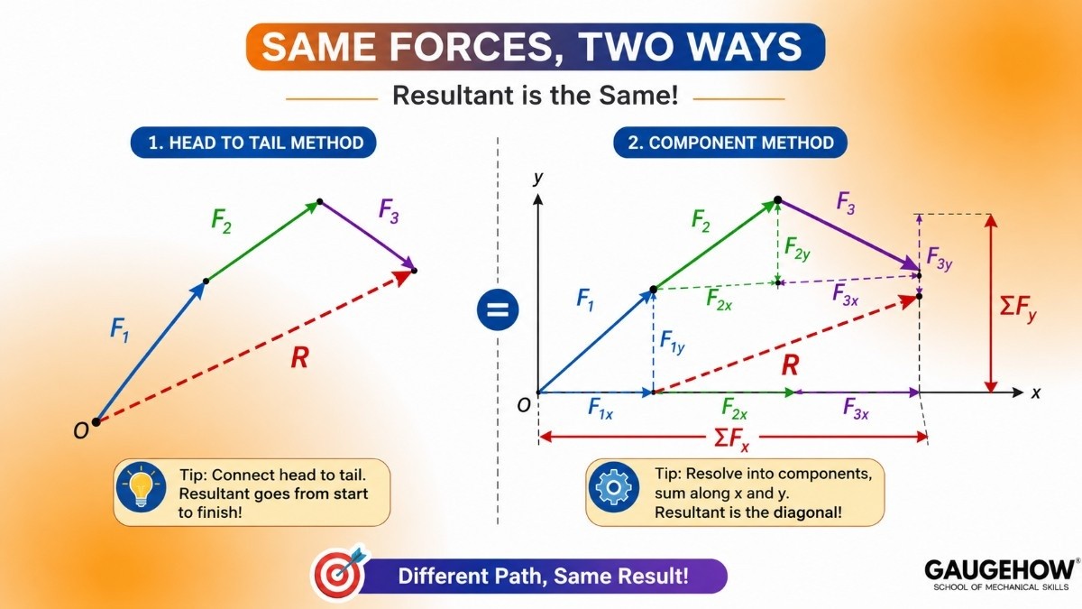
Resolve every force into x and y components, with correct signs.
Add all the x components: ΣFx = F1x + F2x + F3x + ...
Add all the y components: ΣFy = F1y + F2y + F3y + ...
Combine:
R = √((ΣFx)² + (ΣFy)²) tan α = ΣFy / ΣFx
Where:
R is the magnitude of the resultant force in newtons (N)
ΣFx is the algebraic sum of all horizontal components (N)
ΣFy is the algebraic sum of all vertical components (N)
α is the angle of the resultant measured from the x axis, in degrees
The symbol Σ is the Greek letter sigma and just means add them all up.
Solved mini example
Three forces act at a point: 60 N along the positive x axis, 40 N at 60 degrees, and 50 N at 150 degrees. Find the resultant.
Force 1: Fx = 60, Fy = 0
Force 2: Fx = 40 cos 60° = 20, Fy = 40 sin 60° = 34.64
Force 3: Fx = 50 cos 150° = −43.3, Fy = 50 sin 150° = 25
ΣFx = 60 + 20 − 43.3 = 36.7 N and ΣFy = 0 + 34.64 + 25 = 59.64 N
R = √(36.7² + 59.64²) = √(1347 + 3557) = √4904 = 70.0 N
tan α = 59.64 / 36.7 = 1.625, so α = 58.4 degrees from the x axis
Both sums came out positive, so the resultant points up and to the right, into the first quadrant. Always sketch the direction at the end. A calculator will happily give you an angle in the wrong quadrant if you do not check.
Where engineers use it
Every finite element solver on earth runs this same component addition, just millions of times per second. When you set up a load case in a simulation tool, you are handing the software your ΣFx and ΣFy. Learning it by hand first is what lets you spot a wrong result later.
Graphical Method of Finding the Resultant
The graphical method finds the resultant by drawing the forces to scale and measuring the answer with a ruler and protractor.
It sounds old-fashioned, and for calculation work it is. But it builds physical intuition that no formula can, and it is still used for quick site checks and for verifying a computed answer.
How it works
Choose a scale, for example 1 cm = 10 N.
Draw each force as an arrow of the correct length and direction.
Connect them head to tail.
The closing arrow from the very first tail to the very last head is the resultant.
Measure its length, convert back using your scale, and measure its angle.
The three laws that follow are all versions of this same drawing idea, for two forces, for two forces again, and for many forces.
Accuracy depends entirely on how carefully you draw, which is why the analytical method wins for real numbers. Use graphical work to sanity check, not to size a bolt.
Parallelogram Law of Forces
The parallelogram law states that if two forces acting at a point are represented in magnitude and direction by the two adjacent sides of a parallelogram, then their resultant is represented by the diagonal of that parallelogram drawn from the same point.
Real-life picture: two tugboats pulling one ship, ropes spreading outward at an angle. The ship moves along a path between the two ropes. That path is the diagonal.
The formula
For two forces P and Q with angle θ between them:
R = √(P² + Q² + 2PQ cos θ)
And the angle of the resultant from force P:
tan β = (Q sin θ) / (P + Q cos θ)
Where:
P and Q are the two force magnitudes in newtons (N)
θ is the angle between the two forces, in degrees
R is the resultant in newtons (N)
β (beta) is the angle between R and P, in degrees
Solved mini example
Two forces of 80 N and 60 N act at a point with 60 degrees between them.
R = √(80² + 60² + 2 × 80 × 60 × cos 60°)
R = √(6400 + 3600 + 9600 × 0.5)
R = √(6400 + 3600 + 4800) = √14800 = 121.7 N
tan β = (60 × sin 60°) / (80 + 60 × cos 60°) = 51.96 / 110 = 0.472
β = 25.3 degrees from the 80 N force
Two quick sense checks worth remembering. If θ = 0, the forces point the same way and R = P + Q. If θ = 180, they oppose and R = P − Q. Your answer should always sit between those two limits.
Where engineers use it
Crane rigging with two slings, cable-stayed bridge anchor points, and towing arrangements all use the parallelogram law to find the true load on the connection point.
[IMAGE: parallelogram of forces with P along the base, Q as the adjacent side at angle theta, dashed lines completing the parallelogram, and the diagonal drawn as resultant R with angle beta from P]
Triangle Law of Forces
The triangle law states that if two forces acting on a body are represented by two sides of a triangle taken in order, then the third side taken in the opposite order represents their resultant.
This is the same truth as the parallelogram law, drawn more economically. Instead of completing a full parallelogram, you place the tail of the second force at the head of the first and close the shape.
Taken in order means head to tail, following the flow. The closing side runs the other way, from the start point to the finish point.
There is an important cousin worth knowing. If three forces acting at a point can be drawn as a closed triangle, their resultant is zero and the body is in equilibrium. This is called the triangle law of equilibrium, and it is the visual partner of Lami's Theorem.
Where engineers use it
Roof truss joint checks, tent and guy-wire tensions, and quick verification that three-member joints balance.
[IMAGE: two force vectors drawn head to tail forming two sides of a triangle, with the closing third side drawn in the opposite direction and labelled resultant R]
Polygon Law of Forces
The polygon law of forces extends the triangle law to any number of forces. It states that if several forces acting at a point are represented in magnitude and direction by the sides of a polygon taken in order, then their resultant is represented by the closing side taken in the opposite order.
Two forces make a triangle. Five forces make a pentagon. The rule never changes: draw them head to tail, and whatever gap is left is your resultant.
The key insight
If the polygon closes on its own, with no gap between the last head and the first tail, then the resultant is zero and the system is in equilibrium.
This single idea is how engineers eyeball whether a joint is balanced before doing any calculation. A closed polygon means balance. An open polygon means the body will accelerate in the direction of that gap.
Solved mini example
Four forces act at a point: 30 N east, 40 N north, 20 N west, 10 N south. Are they in equilibrium?
ΣFx = +30 − 20 = 10 N
ΣFy = +40 − 10 = 30 N
R = √(10² + 30²) = √1000 = 31.6 N
The polygon does not close, so there is no equilibrium. The resultant is 31.6 N pointing north-east at tan α = 30/10, giving α = 71.6 degrees.
Where engineers use it
Pipe support systems with loads coming from many directions, cable networks, and multi-rope lifting arrangements are all checked this way before the numbers are run.
[IMAGE: four force vectors drawn head to tail forming an open polygon, with a dashed closing arrow from the first tail to the last head labelled resultant R]
Key Takeaways
Resolving a force means splitting it into parts along chosen directions. Composition means combining forces into one resultant.
Rectangular components use perpendicular axes: Fx = F cos θ and Fy = F sin θ.
On an inclined plane, tilt your axes with the slope. Weight splits into W sin α along the surface and W cos α into the surface.
The resultant is the single force that replaces all others without changing the effect.
The analytical method is exact: add all x components, add all y components, then combine with Pythagoras.
Signs carry direction. Right and up are positive, left and down are negative. Most errors here are sign errors.
The parallelogram, triangle and polygon laws are three views of the same head to tail drawing idea.
A closed force polygon means zero resultant, which means equilibrium.
Quick Revision Box
Horizontal component: Fx = F cos θ
Vertical component: Fy = F sin θ
Magnitude from components: F = √(Fx² + Fy²)
Direction from components: tan θ = Fy / Fx
On an incline: along plane = W sin α, perpendicular to plane = W cos α
Resultant of many forces: R = √((ΣFx)² + (ΣFy)²)
Direction of resultant: tan α = ΣFy / ΣFx
Parallelogram law: R = √(P² + Q² + 2PQ cos θ)
Resultant angle from P: tan β = (Q sin θ) / (P + Q cos θ)
Equilibrium condition: ΣFx = 0 and ΣFy = 0
Practice Corner
Why do engineers prefer rectangular components over any other pair of directions?
A 200 N force acts at 45 degrees to the horizontal. Find its horizontal and vertical components.
Two forces of 5 N and 12 N act at right angles at a point. What is the magnitude of their resultant?
If a force polygon drawn for five forces closes perfectly, what does that tell you about the body?
A 100 kg crate sits on a 15 degree ramp. What force tries to slide it down the slope?
Answers
Because the two directions are at 90 degrees, neither component has any effect along the other. That means you can add all the x parts and all the y parts separately without any cross terms, which turns a geometry problem into simple arithmetic.
Fx = 200 cos 45° = 141.4 N and Fy = 200 sin 45° = 141.4 N. At 45 degrees the two components are always equal.
R = √(5² + 12²) = √169 = 13 N, acting at tan α = 12/5, so α = 67.4 degrees from the 5 N force.
The resultant is zero, so the body is in equilibrium. It will not start moving or accelerate.
W = 100 × 9.81 = 981 N. Sliding component = 981 × sin 15° = 981 × 0.259 = 254 N.
Where to Practise This Further
Force resolution is one of those topics that only sticks once you have solved twenty problems, not two. Work through the free MCQ practice tests to drill the component and resultant calculations under time pressure, and check the engineering interview question bank for how these concepts get asked in placement rounds.
When you are ready to see the same maths running inside real software, the Fusion 360 course shows how load directions are applied to a model, and the FEA with ANSYS course takes the component idea all the way to full static structural analysis. If you would rather automate the arithmetic, Python for Mechanical Engineers covers scripting these calculations in a few lines.
Students planning a design career should also browse the Mechanical Engineer hub and the Design Engineer track to see where statics fits into the bigger picture.
Internal links:
Force systems and types of forces in engineering mechanics
Equilibrium of particles and free body diagrams
Friction, angle of repose and inclined plane problems
Practice tests: https://gaugehow.com/practice
Interview Q&A hub: https://gaugehow.com/interview