Engineering Mechanics
Direction Cosines Explained Simply for Engineering Mechanics
In 2D, saying a force points "at 30 degrees above the horizontal" is enough. One angle tells the whole story. But step into 3D, like a cable running from a corner of a room to a hook on the ceiling, and one angle can no longer describe the direction.
To pin down a direction in 3D, we use direction cosines. They describe which way a vector points by the angles it makes with the x, y, and z axes.
In our last lesson we resolved vectors into components, which is easy in 2D. Direction cosines are how we handle direction cleanly in 3D, where real machine parts and structures actually live.
By the end of this lesson you will know what direction cosines are, how to calculate them, the neat identity that connects them, and how engineers use them to point a force in three dimensions.
What Are Direction Cosines?
Direction cosines are the cosines of the angles that a vector makes with the x, y, and z axes.
A vector in 3D makes three angles with the three axes:
The angle with the x-axis is usually called α (alpha).
The angle with the y-axis is usually called β (beta).
The angle with the z-axis is usually called γ (gamma).
The direction cosines are simply the cosines of these three angles, and they are given the short names l, m, and n:
l = cos α
m = cos β
n = cos γ
So instead of writing three angles, we work with three numbers. These three numbers together lock down the exact direction of the vector in space. Think of them as a 3D address for "which way," the same way coordinates are an address for "where."
Why One Angle Is Not Enough in 3D
In 2D, a direction lives on a flat plane, so a single angle from the x-axis fixes it completely.
In 3D, a direction can tilt up, down, left, right, forward, and back, all at once. One angle cannot capture all of that. You need to know how the vector relates to each of the three axes.
Picture standing in the corner of a room and pointing at a spot on the far ceiling. Your arm makes one angle with the floor line going right, another with the floor line going forward, and another with the vertical wall edge. All three angles together describe exactly where you are pointing. Miss one, and the direction is ambiguous.
That is why 3D needs three direction cosines, one for each axis.
The Formulas: Finding Direction Cosines
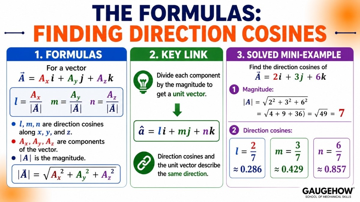
For a vector A = Ax i + Ay j + Az k, each direction cosine is the matching component divided by the magnitude of the vector.
l = Ax / |A|
m = Ay / |A|
n = Az / |A|
l, m, n are the direction cosines along x, y, and z.
Ax, Ay, Az are the components of the vector.
|A| is the magnitude, found with |A| = √(Ax² + Ay² + Az²).
Notice something familiar. Dividing each component by the magnitude is exactly how we found a unit vector a few lessons ago. So the direction cosines are just the components of the unit vector. In fact, the unit vector can be written directly as:
â = l i + m j + n k
This is a lovely link. Direction cosines and the unit vector are two ways of describing the same thing: pure direction.
Solved Mini-Example
Find the direction cosines of A = 2i + 3j + 6k.
Find the magnitude: |A| = √(2² + 3² + 6²) = √(4 + 9 + 36) = √49 = 7
l = 2 / 7, which is about 0.286
m = 3 / 7, which is about 0.429
n = 6 / 7, which is about 0.857
So the direction cosines are roughly 0.286, 0.429, and 0.857. These three numbers now fully describe the vector's direction in 3D.
The Key Identity: l² + m² + n² = 1
Here is the most important fact about direction cosines, and a great way to check your work.
The squares of the three direction cosines always add up to exactly 1:
l² + m² + n² = 1
Why does this always hold? Because l, m, and n are the components of a unit vector, and a unit vector has a length of 1. Squaring and adding its components must give 1, straight from the Pythagoras theorem.
Quick Check
Using our example with l = 2/7, m = 3/7, n = 6/7:
l² + m² + n² = (4/49) + (9/49) + (36/49) = 49/49 = 1
It checks out. If your direction cosines ever fail this test, you have made an error somewhere. This one identity catches mistakes fast, so use it every time.
Building a Force from Direction Cosines
Direction cosines are not just for describing directions. They let you point a force exactly where you want it in 3D, just like the unit vector did in 2D.
Once you know the size of a force and its direction cosines, the full force vector is:
F = F (l i + m j + n k)
F on the left is the full force vector.
F on the right (plain letter) is the size of the force, in newtons (N).
l, m, n are the direction cosines of the line the force acts along.
Solved Mini-Example
A cable pulls with 140 N along a direction with cosines l = 2/7, m = 3/7, n = 6/7. Find the force vector.
x-part: 140 × (2/7) = 40 N
y-part: 140 × (3/7) = 60 N
z-part: 140 × (6/7) = 120 N
Write the force: F = 40i + 60j + 120k (in newtons)
So the 140 N pull becomes 40 N, 60 N, and 120 N along the three axes. You have turned a 3D direction and a size into clean components ready for a force problem. This is the standard way engineers set up cables and slanted members in 3D.
Direction Cosines and Angles
Because l = cos α, you can also work backward to find the actual angles a vector makes with each axis.
Just take the inverse cosine of each direction cosine:
α = cos⁻¹(l)
β = cos⁻¹(m)
γ = cos⁻¹(n)
For our example, α = cos⁻¹(0.286), which is about 73 degrees from the x-axis. This is useful when a drawing gives you angles and you need the direction, or when you have the direction and need to report the angles. The two forms convert freely.
Where Engineers Use Direction Cosines
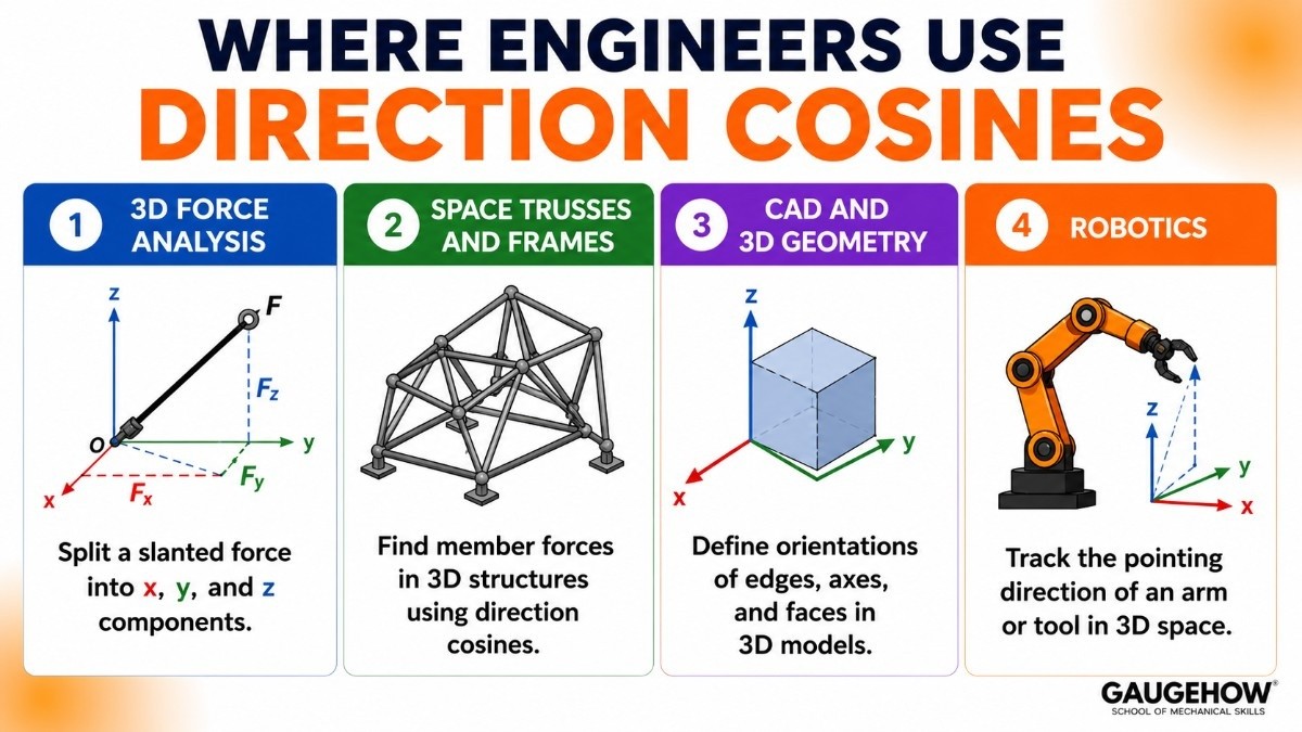
Direction cosines are the backbone of 3D force work:
3D force analysis: Any cable, strut, or member that runs at a slant in space is set up using direction cosines to split its force into x, y, and z parts.
Space trusses and frames: Structures that are not flat need direction cosines at every member, work that tools like FEA with ANSYS handle across a whole model.
CAD and 3D geometry: Orientations of edges, axes, and faces in tools like Fusion 360 are described with direction cosines.
Robotics: The pointing direction of an arm or tool in 3D space is tracked with direction cosines, often computed in Python.
Common Mistakes to Avoid
Forgetting the identity check. Always confirm l² + m² + n² = 1. If it does not equal 1, something is wrong.
Dividing by the wrong magnitude. Each component must be divided by the magnitude of the same vector.
Mixing up the angles. α is measured from the x-axis, β from the y-axis, and γ from the z-axis. Keep them in order.
Dropping the z-part in 3D. All three direction cosines are needed. Leaving one out breaks the direction.
Frequently Asked Questions
What are direction cosines in simple words? They are the cosines of the angles a vector makes with the x, y, and z axes. Three numbers (l, m, n) that fully describe a direction in 3D.
How do you find direction cosines? Divide each component of the vector by its magnitude: l = Ax/|A|, m = Ay/|A|, n = Az/|A|.
What is the relation l² + m² + n² = 1? It is an identity that always holds, because direction cosines are the components of a unit vector, which has a length of 1.
Are direction cosines the same as a unit vector? Yes. The direction cosines are exactly the components of the unit vector along the same direction.
Why are direction cosines used in engineering? Because they describe direction in 3D, which single angles cannot do. They are essential for setting up 3D forces on cables and members.
Key Takeaways
Direction cosines are the cosines of the angles a vector makes with the x, y, and z axes.
They are named l, m, n, found by dividing each component by the magnitude.
Direction cosines are the same as the components of the unit vector.
The identity l² + m² + n² = 1 always holds and is a fast error check.
A 3D force is built as F = F (l i + m j + n k).
One angle is not enough in 3D, so all three direction cosines are needed.
Quick Revision Box
Direction cosines: l = cos α, m = cos β, n = cos γ
From components: l = Ax/|A|, m = Ay/|A|, n = Az/|A|
Identity: l² + m² + n² = 1
Unit vector: â = l i + m j + n k
Force in 3D: F = F (l i + m j + n k)
Practice Corner
Find the direction cosines of A = 1i + 2j + 2k.
What is the value of l² + m² + n² for any vector?
A 90 N force acts along direction cosines l = 1/3, m = 2/3, n = 2/3. Find the force vector.
What does the direction cosine l equal, in terms of an angle?
Are direction cosines the same as the components of a unit vector?
<details> <summary>Answers</summary>
|A| = √(1² + 2² + 2²) = √9 = 3. So l = 1/3, m = 2/3, n = 2/3.
Always 1.
F = 90 × (1/3) i + 90 × (2/3) j + 90 × (2/3) k = 30i + 60j + 60k N.
l = cos α, the cosine of the angle the vector makes with the x-axis.
Yes, they are exactly the same.
</details>
Conclusion
Direction cosines are how engineers describe direction in three dimensions, using the angles a vector makes with each axis. Master the l, m, n formulas and the l² + m² + n² = 1 check, and you can point any force precisely in 3D, ready for real space-frame and cable problems.
Want to make it stick? Visit the Mechanical Engineer learning hub at GaugeHow and try the practice questions before moving on.
What's Next
Next up: a Trigonometry Refresher, where we revisit the sine, cosine, and tangent rules that power all of these vector calculations.
Internal links: FEA with ANSYS → https://gaugehow.com/course/fea-finite-element-analysis-with-ansys | 3D modelling in Fusion 360 → https://gaugehow.com/course/fusion-360 | Python for Mechanical Engineers → https://gaugehow.com/course/python-for-mechanical-engineers-robotics | Mechanical Engineer Hub → https://gaugehow.com/mech | Practice tests → https://gaugehow.com/practice