Engineering Mechanics
Polygon Law of Forces Explained with Examples
Two forces are easy. Draw a triangle and you are done. But real joints rarely carry two forces. A crane hook might carry five. A truss node might carry six.
The polygon law of forces is what handles all of them at once. It takes the simple triangle idea and stretches it to any number of forces, without adding a single new rule.
This guide covers the statement of the law, how to construct the polygon step by step, why it works, what happens when the polygon closes, where engineers actually use it, and where it stops being valid. Plain language, worked numbers, and the traps pointed out before you hit them.
What Is the Polygon Law of Forces?
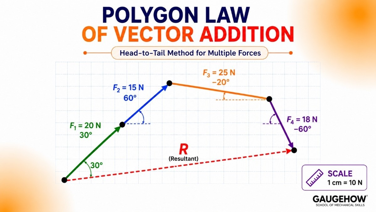
The polygon law of forces states that if a number of forces acting at a point are represented in magnitude and direction by the sides of a polygon taken in order, then their resultant is represented in magnitude and direction by the closing side of the polygon taken in the opposite order.
That sentence carries a lot, so unpack it slowly.
Represented in magnitude and direction means each force becomes a line whose length matches its size at a chosen scale, and whose angle matches its direction.
Taken in order means head to tail. Each force starts exactly where the previous one ended.
The closing side is the line joining the very first tail to the very last head.
In the opposite order means the resultant arrow points backwards compared with the way you travelled around the figure. You walked from start to finish, so the resultant points from start to finish while all the others point the way you walked.
Here is the everyday picture. Imagine walking around a park: 50 paces north, 30 paces east, 20 paces south-west. Your total displacement is not the distance you walked. It is the straight line from where you began to where you stopped. Forces combine exactly the same way, and the polygon law is that idea written formally.
Statement of the Law in Simple Words
If you only remember one version, remember this one.
Draw all the forces head to tail. Whatever gap is left between the finish and the start is the resultant.
Two forces make a triangle. Three make a quadrilateral. Five make a hexagon. The number of sides changes, the rule does not.
That also explains something students often ask. The triangle law is not a different law. It is the polygon law with exactly two forces, where the polygon happens to have three sides.
How to Construct a Force Polygon
Six steps, done with a ruler, a protractor and a sharp pencil.
Choose a scale and write it on the drawing, for example 1 cm = 20 N. Pick it so the largest force is somewhere between 6 cm and 12 cm long.
Draw the first force to scale at its correct angle, with an arrowhead showing its direction.
Start the second force at the head of the first, keeping its own true length and angle.
Continue for every remaining force, each one beginning where the previous one ended.
Draw the closing line from the tail of the very first force to the head of the very last one. Put the arrowhead on the end nearest the last head.
Measure and convert. Multiply the closing length by your scale for the magnitude, and read the angle with a protractor.
Two rules that must not be broken. When you move a force to its new starting point, you may slide it but never rotate it, so its angle stays identical. And every force in one polygon must use the same scale.
Worked construction
Four forces act at a point: 60 N at 0 degrees, 40 N at 70 degrees, 50 N at 145 degrees and 30 N at 230 degrees.
Scale: 1 cm = 10 N.
Draw 6.0 cm horizontally right.
From that head, draw 4.0 cm at 70 degrees.
From that head, draw 5.0 cm at 145 degrees.
From that head, draw 3.0 cm at 230 degrees.
Join the original start to the final head. Measure roughly 4.2 cm at about 71 degrees.
Convert: 4.2 × 10 = 42 N at about 71 degrees.
Check that against the calculation. Adding components gives ΣFx = 60 + 13.7 − 41.0 − 19.3 = 13.4 N and ΣFy = 0 + 37.6 + 28.7 − 23.0 = 43.3 N, so R = 45.3 N at 72.8 degrees. The drawing landed within a couple of newtons, which is exactly the accuracy you should expect from careful graphical work.
Why the Polygon Law Works
The law is not a new principle. It is the triangle law applied over and over.
Take four forces. Combine the first two head to tail, and the triangle law gives you their resultant. Now combine that resultant with the third force, and the triangle law gives you a new resultant. Combine that with the fourth, and you have the final answer.
If you draw all of those intermediate resultants, then rub them out, what remains on the page is exactly the force polygon. The intermediate lines were never necessary, because each one simply passed the running total along to the next step.
That is the whole proof. The polygon law is repeated triangle addition with the working erased.
Order does not matter
Here is a fact worth testing yourself, because it feels wrong until you see it.
You can draw the forces in any order and the closing line comes out identical. Put the 50 N force first or last, and the start point and finish point are unchanged. The polygon looks like a completely different shape, but the resultant is the same length at the same angle.
This happens because vector addition is commutative, meaning the order of adding does not change the total. It also gives you a free check. Redraw the polygon in a different order, and if the closing line differs, one of your two drawings has an error in it.
What Happens When the Polygon Closes
This is the most useful result in the topic, and it deserves its own section.
If the force polygon closes on itself, with the head of the last force landing exactly on the tail of the first, then the resultant is zero. There is no closing line to draw, because there is no gap.
A zero resultant means the body is in equilibrium. It will not start moving and it will not accelerate.
This is called the converse of the polygon law, and it is what engineers reach for in practice. You do not usually want to know the resultant at a crane hook. You want to know whether the hook is balanced, and a closed polygon answers that at a glance.
The reverse is just as informative. An open polygon means the body is unbalanced, and the gap tells you both things you need. Its length gives the size of the unbalanced force, and its direction is the direction the body will accelerate.
A gap of 1.8 cm at a scale of 1 cm = 100 N means an unbalanced force of about 180 N. No equations required.
One clarification worth making. Equilibrium does not mean stationary. It means not accelerating. A lift travelling upward at constant speed has a perfectly closed force polygon.
Difference Between Triangle, Parallelogram and Polygon Law
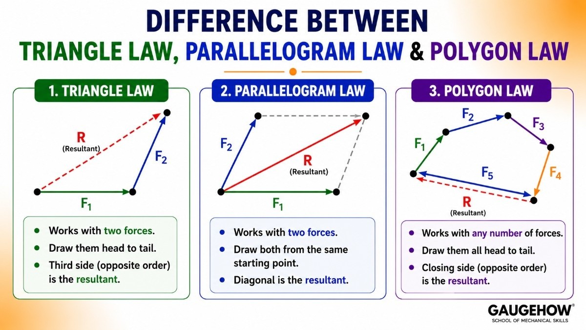
All three describe the same underlying vector addition, so they never disagree. They differ only in how many forces they handle and how you draw them.
Triangle law works with two forces. Draw them head to tail and the third side of the triangle, taken in the opposite order, is the resultant.
Parallelogram law also works with two forces, but draws both from the same starting point. Complete the parallelogram and the diagonal from that point is the resultant.
Polygon law works with any number of forces. Draw them all head to tail and the closing side is the resultant.
For two forces you may use whichever you prefer, since the answers are identical. The parallelogram construction is more natural when both forces genuinely act from the same physical point, such as a bolt or a hook. Beyond two forces, the polygon law is the only practical choice, because a parallelogram cannot be extended to five forces without becoming a mess.
Checking a Force Polygon Analytically
Graphical accuracy depends on your pencil, so it is good practice to verify the drawing with numbers.
Resolve every force into components, add them separately, then combine:
R = √((ΣFx)² + (ΣFy)²) tan α = ΣFy / ΣFx
Where:
ΣFx is the algebraic sum of all horizontal components, in newtons (N)
ΣFy is the algebraic sum of all vertical components, in newtons (N)
R is the resultant force, in newtons (N)
α (alpha) is its angle from the x axis, in degrees
For equilibrium, the polygon closing is exactly equivalent to:
ΣFx = 0 ΣFy = 0
The two statements say the same thing in different languages. One is drawn, one is calculated. Seeing that they are equivalent is the point at which most students stop treating them as separate topics.
Solved example
Five forces act at a point: 80 N at 0°, 60 N at 90°, 80 N at 180°, 60 N at 270°, and 25 N at 45°. Do they balance?
The first and third cancel: 80 − 80 = 0
The second and fourth cancel: 60 − 60 = 0
Only the 25 N force remains: Fx = 17.7, Fy = 17.7
R = √(17.7² + 17.7²) = 25 N at 45 degrees
The polygon does not close, and the gap is precisely the leftover 25 N force. Four of the five forces formed a closed rectangle among themselves, which is a nice visual demonstration of what balance looks like.
Where Engineers Use the Polygon Law
It survives in practice because it answers a yes or no question faster than a calculation does.
Truss joint checks. A node with five members either balances or it does not, and a quick polygon shows which without solving simultaneous equations.
Crane and rigging work. A hook with three or four slings at different angles is checked on site with a sketch before the lift begins.
Cable and guy wire systems. Masts and tents with several anchor cables use it to confirm the top joint is balanced.
Pipe support systems. Loads arrive from several directions at once, and the polygon shows whether the hanger carries a net load.
Checking software output. A rough polygon tells you instantly whether a simulation result points the right way and is the right order of magnitude.
The pattern is the same everywhere. Use the polygon to see and to verify. Use components to produce the number you would sign off on.
Limitations of the Polygon Law
It is a genuinely useful tool, but it does not cover everything.
Concurrent forces only. All forces must pass through a single point. Forces acting at different points on a body create turning effects that the polygon cannot show.
Coplanar forces only. The construction is flat, so it cannot represent a three-dimensional force system on paper.
No moment information. A closed polygon proves the forces balance, but a body can still rotate if the forces form a couple. Full rigid body equilibrium also needs ΣM = 0.
Accuracy limited by drawing. Expect one to three percent error from ruler, protractor and pencil thickness combined.
Gets crowded. With eight or more forces the figure becomes hard to read, which is why Bow's notation exists for labelling large diagrams.
That third point is the one that catches people out. Closed polygon means no acceleration in a straight line. It does not by itself prove the body will not spin.
Common Mistakes to Avoid
Rotating a force while moving it. Sliding an arrow to a new start point is fine. Changing its angle is not.
Drawing the resultant the wrong way round. It runs from the first tail to the last head, against the direction you travelled around the figure.
Forgetting to write the scale. Without it your measurement cannot be converted back into newtons.
Changing scale mid-diagram. Every force must be drawn at the same scale.
Assuming a nearly closed polygon means equilibrium. A small gap is still a real unbalanced force. Measure it rather than dismissing it.
Applying it to non-concurrent forces. If the forces do not meet at one point, the polygon alone cannot settle the question.
Using a blunt pencil. At 1 cm = 100 N, a thick line is worth 20 N of error before you even start measuring.
Key Takeaways
The polygon law says that forces drawn head to tail have a resultant equal to the closing side of the figure.
It is simply the triangle law applied repeatedly, so it is not a separate principle.
The order in which the forces are drawn does not affect the closing line.
A closed polygon means zero resultant, which means equilibrium.
An open polygon gives both the size and the direction of the unbalanced force.
Closing the polygon is the graphical equivalent of ΣFx = 0 and ΣFy = 0.
It applies only to coplanar concurrent forces and says nothing about moments.
Accuracy depends on the drawing, so verify important results with components.
Quick Revision Box
Statement: forces as sides of a polygon taken in order, resultant as the closing side in the opposite order
Construction: head to tail, one consistent scale, arrows never rotated
Resultant: closing line from first tail to last head
Closed polygon: R = 0, body in equilibrium
Open polygon: gap length × scale = unbalanced force
Analytical equivalent: R = √((ΣFx)² + (ΣFy)²) and tan α = ΣFy / ΣFx
Equilibrium equations: ΣFx = 0 and ΣFy = 0
Valid for: coplanar concurrent forces only
Triangle law: the polygon law with just two forces
Frequently Asked Questions
What is the polygon law of forces in simple words?
Draw every force head to tail as an arrow to scale. The single arrow needed to get from the starting point back to the finishing point is the resultant. If no arrow is needed because the shape already closed, the forces balance.
Does the polygon law work for any number of forces?
Yes, as long as all the forces act at a single point and lie in the same plane. Three forces give a quadrilateral, six give a heptagon, and the rule is unchanged.
What does it mean when a force polygon closes?
The resultant is zero, so the body is in equilibrium and will not accelerate. This is the converse of the polygon law and it is the reason the method is used in practice.
Is the polygon law the same as the triangle law?
The triangle law is the polygon law for two forces. Both describe the same head to tail vector addition, just with a different number of sides.
Can I draw the forces in any order?
Yes. The shape changes but the starting point and finishing point do not, so the closing line stays the same. Redrawing in a different order is a useful way to check your work.
Does a closed polygon prove a body will not move at all?
No. It proves the body will not accelerate in a straight line. The body could still rotate if the forces form a couple, so full rigid body equilibrium also needs the sum of moments to be zero.
Practice Corner
State the polygon law of forces in your own words.
Five forces are drawn head to tail and the figure closes exactly. What can you conclude?
At a scale of 1 cm = 40 N, a force polygon leaves a gap of 2.5 cm. What is the unbalanced force?
Why does the order of drawing the forces not change the resultant?
Four forces act at a point: 100 N east, 100 N west, 70 N north, 40 N south. Find the resultant.
Answers
If several forces at a point are drawn head to tail as the sides of a polygon, the line closing the figure, drawn in the opposite sense, represents their resultant in both size and direction.
The resultant is zero, so the forces are in equilibrium and the body will not accelerate in a straight line.
2.5 × 40 = 100 N, acting in the direction of the gap.
Because vector addition is commutative. Rearranging the order changes the shape of the polygon but not where you start or where you finish, so the closing line is identical.
ΣFx = 100 − 100 = 0 and ΣFy = 70 − 40 = 30 N, so the resultant is 30 N due north.
Where to Practise This Further
Polygon constructions become quick once you have drawn a dozen of them, since the skill is technique rather than theory. Drill resultant and equilibrium questions with the free MCQ practice tests, and see how these come up in placement rounds in the engineering interview question bank.
Modern solvers automate the same vector addition, and the link is worth seeing. The Fusion 360 course shows how load directions are applied to a model, and the FEA with ANSYS course carries this logic into full static structural analysis. If you would rather plot force polygons from code, Python for Mechanical Engineers covers calculating and drawing them together.
Students planning a design career can also browse the Mechanical Engineer hub and the Design Engineer track to see where statics fits into the wider skill set.
Internal links:
Graphical method of finding the resultant force
Resultant force formula and examples
Analytical method of finding the resultant force
Practice tests: https://gaugehow.com/practice
Interview Q&A hub: https://gaugehow.com/interview