Engineering Mechanics
Rectangular Components of a Force Explained Simply
Ask any engineer what the most used calculation in statics is, and the answer will not be some grand theorem. It will be splitting a slanted force into a horizontal part and a vertical part.
Rectangular components are the reason that slanted forces stop being scary. Once you can break a force into two perpendicular pieces, adding ten forces becomes as easy as adding ten numbers.
This guide covers what rectangular components are, the formulas, the sign convention that trips up most students, how to handle inclined planes and 3D forces, and how the whole thing feeds into finding a resultant force. Plain language, solved examples, no shortcuts skipped.
What Are Rectangular Components of a Force?
Rectangular components are the two parts of a force measured along two directions that are perpendicular to each other, normally the horizontal x axis and the vertical y axis.
The word rectangular comes from the shape you get when you draw them. Sketch the force as a slanted arrow, drop a dashed line down to the x axis and across to the y axis, and you have drawn a rectangle with the force as its diagonal.
Here is the everyday version. You are pushing a lawnmower. Your arms push down the handle at an angle. Part of that push drives the mower forward. The rest of it presses the mower into the grass. Those two parts are the rectangular components of your push.
Nothing about the force changed. You just described one awkward arrow as two convenient ones.
[IMAGE: a person pushing a lawnmower with the handle at an angle, showing the applied force F as a slanted arrow, with a dashed horizontal arrow Fx driving the mower forward and a dashed vertical arrow Fy pressing it into the ground]
Why Forces Are Resolved into Rectangular Components
There is one reason above all others, and it is worth understanding rather than memorising.
Because the x and y directions are at 90 degrees, a force along x has zero effect along y. They never interfere with each other. That means you can treat a two-dimensional problem as two separate one-dimensional problems and add plain numbers instead of doing geometry.
Three practical payoffs:
A beam only feels the vertical part of a slanted cable pull. Resolve, and you get the number the beam actually cares about.
A bolt is checked for shear in one direction and tension in another. Resolve, and each check gets its own clean value.
Ten forces at ten different angles reduce to two sums. No triangles, no protractors.
If you pick any other pair of directions that are not perpendicular, each component starts leaking into the other and the arithmetic falls apart. Right angles are what keep it clean.
Rectangular Components Formula
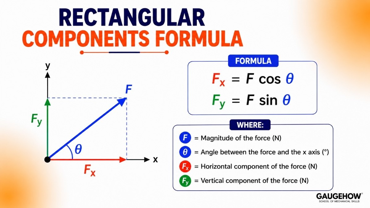
For a force F acting at an angle θ measured from the positive x axis:
Fx = F cos θ Fy = F sin θ
Where:
F is the magnitude of the force, in newtons (N)
θ (theta) is the angle between the force and the x axis, in degrees
Fx is the horizontal component, in newtons (N)
Fy is the vertical component, in newtons (N)
The memory rule that never fails: the component next to the angle uses cosine, the component opposite the angle uses sine. If the angle is measured from the vertical instead of the horizontal, the two swap over. Always check which line the angle is drawn from before you reach for cos.
Solved example
A cable pulls a crate with a force of 250 N at 40 degrees above the ground. Find the components.
Fx = 250 × cos 40° = 250 × 0.766 = 191.5 N
Fy = 250 × sin 40° = 250 × 0.643 = 160.7 N
So the crate is being dragged forward with 191.5 N and lifted with 160.7 N at the same time. That lifting part is why dragging at an angle reduces friction, and why the pull angle matters so much in rigging work.
How to Find Magnitude and Direction from Components
Resolution works both ways. If you already know the components, you can rebuild the original force:
F = √(Fx² + Fy²) tan θ = Fy / Fx
Where F is the magnitude in newtons and θ is the angle from the x axis in degrees.
The first formula is just Pythagoras applied to the rectangle. The second is basic trigonometry on the same triangle.
Solved example
A force has components Fx = 9 N and Fy = 12 N. Find the force.
F = √(9² + 12²) = √(81 + 144) = √225 = 15 N
tan θ = 12 / 9 = 1.333, so θ = 53.1 degrees above the x axis
Always finish by sketching the arrow roughly. A quick sketch catches a wrong quadrant instantly, and calculators do not warn you about quadrants.
Sign Convention for Force Components
This is where most marks are lost, so slow down here.
Components carry direction in their sign:
Pointing right is positive x, pointing left is negative x
Pointing up is positive y, pointing down is negative y
A force at 150 degrees points up and to the left, so its Fx is negative and its Fy is positive. A force at 220 degrees points down and to the left, so both are negative.
Two habits that eliminate almost every sign error:
Draw the x and y axes on your diagram before touching the calculator, and mark which way is positive.
After computing each component, look at your sketch and ask whether the sign matches the direction you can see. If the arrow clearly points left and your Fx came out positive, you have a mistake.
Weight is the one to watch. It always acts downward, so it is always negative y, no matter how the rest of the problem is drawn.
Rectangular Components on an Inclined Plane
A body on a slope looks like a hard problem until you rotate your thinking.
Instead of forcing the weight to fit horizontal and vertical axes, tilt the axes to fit the slope. Take x along the plane and y perpendicular to the plane. They are still at 90 degrees to each other, so everything you have learned still applies.
For a body of weight W on a plane inclined at angle α to the horizontal:
Component along the plane = W sin α Component perpendicular to the plane = W cos α
Where W is the weight in newtons, equal to mass × 9.81, and α is the slope angle in degrees.
The first component is what tries to slide the body down. The second is what presses it into the surface, and it is what the normal reaction has to balance.
Solved example
A 120 kg drum sits on a ramp inclined at 18 degrees.
W = 120 × 9.81 = 1177.2 N
Along the plane = 1177.2 × sin 18° = 1177.2 × 0.309 = 363.8 N
Perpendicular to the plane = 1177.2 × cos 18° = 1177.2 × 0.951 = 1119.5 N
Note what happens as the slope gets steeper. The sliding component grows and the pressing component shrinks, which is exactly why steep ramps become dangerous. The maths matches the intuition.
Difference Between Resolution and Composition of Forces

These two words describe opposite journeys along the same road.
Resolution of forces means taking one force and splitting it into components. One arrow becomes two.
Composition of forces means taking several forces and combining them into a single resultant force. Many arrows become one.
In practice you almost always do both in the same problem. You resolve everything into components, add the components, then compose the answer back into one resultant. Rectangular components are the common language that lets those two steps connect.
How to Find the Resultant Force Using Rectangular Components
The resultant force is the single force that has exactly the same effect as all the forces acting together. Its symbol is R and its unit is the newton.
The method has four steps and never changes, no matter how many forces there are.
Resolve every force into Fx and Fy, with correct signs.
Add all the horizontal components: ΣFx
Add all the vertical components: ΣFy
Combine them:
R = √((ΣFx)² + (ΣFy)²) tan α = ΣFy / ΣFx
Where ΣFx and ΣFy are the algebraic sums of the components in newtons, R is the resultant in newtons, and α is its angle from the x axis in degrees. The symbol Σ is the Greek letter sigma and simply means add them all together.
Solved example
Three forces act at a point: 70 N along the positive x axis, 50 N at 55 degrees, and 45 N at 160 degrees. Find the resultant.
Force 1: Fx = 70, Fy = 0
Force 2: Fx = 50 cos 55° = 28.7, Fy = 50 sin 55° = 41.0
Force 3: Fx = 45 cos 160° = −42.3, Fy = 45 sin 160° = 15.4
ΣFx = 70 + 28.7 − 42.3 = 56.4 N
ΣFy = 0 + 41.0 + 15.4 = 56.4 N
R = √(56.4² + 56.4²) = √6362 = 79.8 N at tan α = 1, so α = 45 degrees
Both sums are positive, so the resultant points up and to the right. When ΣFx and ΣFy come out equal, the angle is always 45 degrees, which is a handy check.
The equilibrium case
If a body is not accelerating, the resultant must be zero. That gives the two equations behind almost all of statics:
ΣFx = 0 ΣFy = 0
Every support reaction, cable tension and truss member force you will ever calculate comes out of those two lines.
[IMAGE: three force vectors acting at a single point at different angles, with each one shown resolved into dashed x and y components, and a bold resultant arrow R drawn from the point at angle alpha with the labels sigma Fx and sigma Fy along the axes]
Rectangular Components in Three Dimensions
Real machines are not flat, so at some point the second dimension is not enough.
In 3D a force splits into three rectangular components along the x, y and z axes:
Fx = F cos θx Fy = F cos θy Fz = F cos θz
Where θx, θy and θz are the angles the force makes with each axis in degrees. These cosines are called direction cosines.
The magnitude comes back the same way, with one more term:
F = √(Fx² + Fy² + Fz²)
There is also a neat check built into the maths. The three direction cosines always satisfy:
cos²θx + cos²θy + cos²θz = 1
If your three angles do not satisfy that, one of them is wrong. It is a free error check, and worth using every time.
Common Mistakes to Avoid
Using cos when the angle is measured from the vertical. Look at the diagram, not the habit. The component hugging the angle takes cosine.
Dropping the negative sign. A component pointing left or down must carry a minus. Losing it is the number one cause of wrong resultants.
Mixing units. Convert kg to newtons by multiplying by 9.81 before resolving anything.
Adding magnitudes directly. A 30 N and a 40 N force do not give 70 N unless they point the same way.
Trusting the calculator angle blindly. The inverse tangent cannot tell the difference between the first and third quadrants. Your sketch can.
Key Takeaways
Rectangular components are the two parts of a force along perpendicular axes, usually x and y.
Fx = F cos θ and Fy = F sin θ when the angle is measured from the x axis.
Perpendicular directions do not affect each other, which is why the method works so cleanly.
Rebuild a force from components with F = √(Fx² + Fy²) and tan θ = Fy / Fx.
Signs carry direction. Right and up positive, left and down negative.
On a slope, tilt the axes: W sin α slides the body, W cos α presses it down.
Resolution splits one force into parts. Composition combines many forces into a resultant.
A body is in equilibrium when ΣFx = 0 and ΣFy = 0.
Quick Revision Box
Horizontal component: Fx = F cos θ
Vertical component: Fy = F sin θ
Magnitude from components: F = √(Fx² + Fy²)
Direction from components: tan θ = Fy / Fx
On an incline: along plane = W sin α, perpendicular = W cos α
Resultant: R = √((ΣFx)² + (ΣFy)²)
Resultant direction: tan α = ΣFy / ΣFx
Equilibrium: ΣFx = 0 and ΣFy = 0
3D components: Fx = F cos θx, Fy = F cos θy, Fz = F cos θz
Direction cosine check: cos²θx + cos²θy + cos²θz = 1
Frequently Asked Questions
Why are components taken at right angles and not any other angle? Because perpendicular directions are independent. A force along x contributes nothing along y, so the two sums can be done separately. At any other angle the components overlap and you gain nothing over the original problem.
When do I use sine and when do I use cosine? Look at where the angle is drawn from. The component lying along the same line as the angle uses cosine. The component at right angles to it uses sine. Angles from the vertical simply swap the two.
Can a component be bigger than the force itself? No. Since sine and cosine never exceed 1, each rectangular component is always less than or equal to the full force. If your component came out larger, check your calculator mode and your angle.
What is the difference between resolution and composition? Resolution splits one force into components. Composition combines several forces into one resultant. Most problems use resolution first and composition second.
Do rectangular components work for moments too? Yes. Moments are vectors as well, so they can be resolved along axes in exactly the same way. The idea carries straight through into moments, couples and 3D rigid body problems.
Practice Corner
A 400 N force acts at 65 degrees to the horizontal. Find both components.
A force has Fx = −20 N and Fy = 21 N. Find its magnitude and describe its direction.
Why must weight always be treated as a negative y component?
A 60 kg crate rests on a 25 degree slope. What force tries to slide it down?
Two forces act at a point: 100 N at 0 degrees and 100 N at 90 degrees. Find the resultant.
Answers
Fx = 400 cos 65° = 169.0 N and Fy = 400 sin 65° = 362.5 N.
F = √(400 + 441) = √841 = 29 N. Fx is negative and Fy is positive, so it points up and to the left, at tan θ = 21/20, giving about 46.4 degrees above the negative x axis.
Because gravity always pulls straight down, and down is the negative y direction under the standard convention. It never changes with the geometry of the problem.
W = 60 × 9.81 = 588.6 N. Sliding component = 588.6 × sin 25° = 588.6 × 0.423 = 248.9 N.
ΣFx = 100 and ΣFy = 100, so R = √20000 = 141.4 N at 45 degrees.
Where to Practise This Further
Force resolution only becomes automatic after you have solved a stack of problems, not a couple. Drill the components and resultants under time pressure with the free MCQ practice tests, and see how these ideas get asked in placement rounds in the engineering interview question bank.
To watch the same maths run inside real software, the Fusion 360 course shows how load directions are applied to a model, and the FEA with ANSYS course carries component thinking into full static structural analysis. If you would rather let code do the arithmetic, Python for Mechanical Engineers covers scripting these calculations.
Students planning a design career can also browse the Mechanical Engineer hub and the Design Engineer track to see where statics fits into the wider skill set.
Internal links:
Force systems and types of forces in engineering mechanics
Resolution and composition of forces explained simply
Equilibrium of particles and free body diagrams
Practice tests: https://gaugehow.com/practice
Interview Q&A hub: https://gaugehow.com/interview