Dial Indicator: Parts, Working, Least Count, Types, Uses

A dial indicator is a contact comparator that shows small linear displacement on a dial. What is a Dial Indicator is defined by that comparison role. The setup work uses it to detect runout, alignment error, and seating change. Many models read 0.01 mm per division, but stiffness and contact angle set repeatability.
Understanding Dial Indicator
Focus area | Use case | Key benefit/takeaway | Industry applications |
Comparator role | Runout, alignment, seating change | Displacement from set zero, not direct size | Machining, assembly, and QA benches |
Parts that control repeatability | Mounting + contact stability | Tip wear, side load, backlash, bezel lock matter | Toolrooms, metrology rooms, fixtures |
Motion conversion | Linear input to dial output | Rack drives pinion, gears rotate pointer | Machine setup, inspection stations |
Least count and reading | Resolution selection + reporting | LC = travel/rev ÷ divisions; read revs + divisions | QC reporting, process capability checks |
Error control | Avoid false low / drift | Cosine, backlash, parallax, zero shift control | Precision grinding, turning, jig boring |
Type selection | Access + contact direction + travel | Plunger for axial reach; lever for tight access | CNC setup, mold shops, aerospace parts |
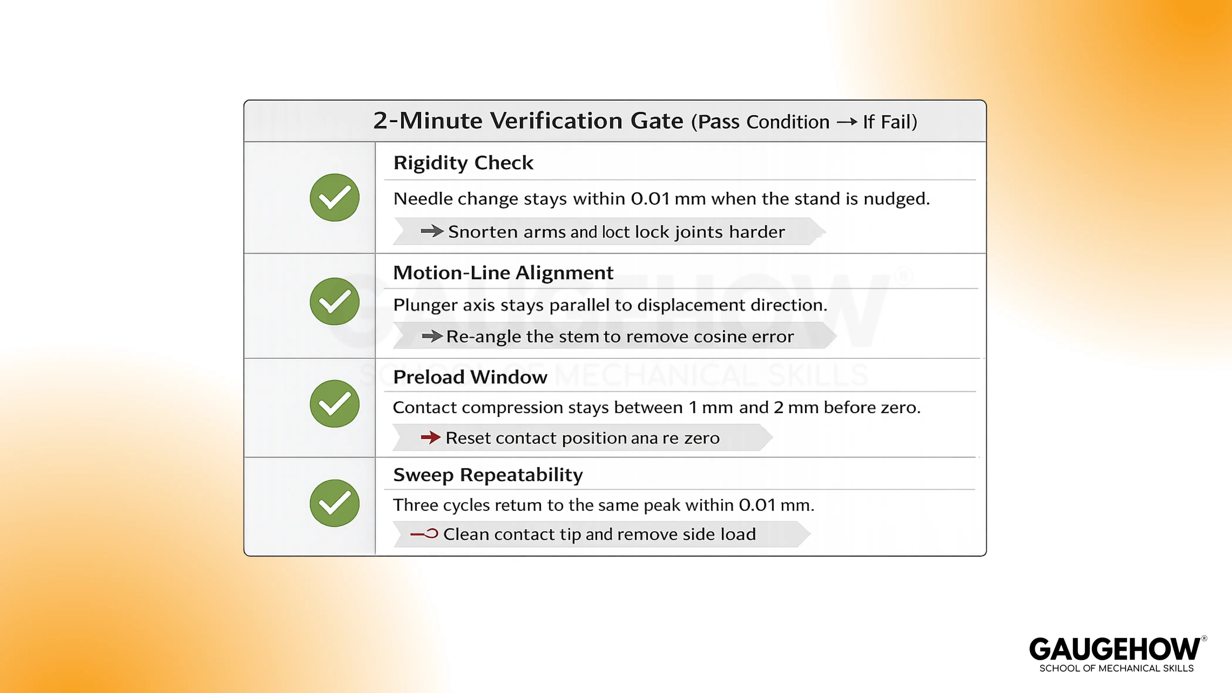
Verification gate | Trust check before recording | Rigidity, alignment, preload, repeat peak | Production lines, incoming inspection |
What is a Dial Indicator?
A dial indicator, also known as a dial gauge, is a spring-loaded contact gauge. The instrument is used to compare displacement relative to a reference. Pointer movement represents change, not absolute size.
In practical checks, “displacement” means surface motion along the plunger axis. That motion can come from rotation, sliding, or seating. During a runout check, a shaft is rotated slowly. Needle swing shows how far the surface wanders at one point.
On a surface plate, a feature is scanned along a line. Trend direction shows whether the surface is rising or falling. Within setups, the tool is used to align parts to an axis. In QC, the tool is used to compare a part to a master.
Dial Indicator Diagram
The diagram of Dial Indicator is added below.
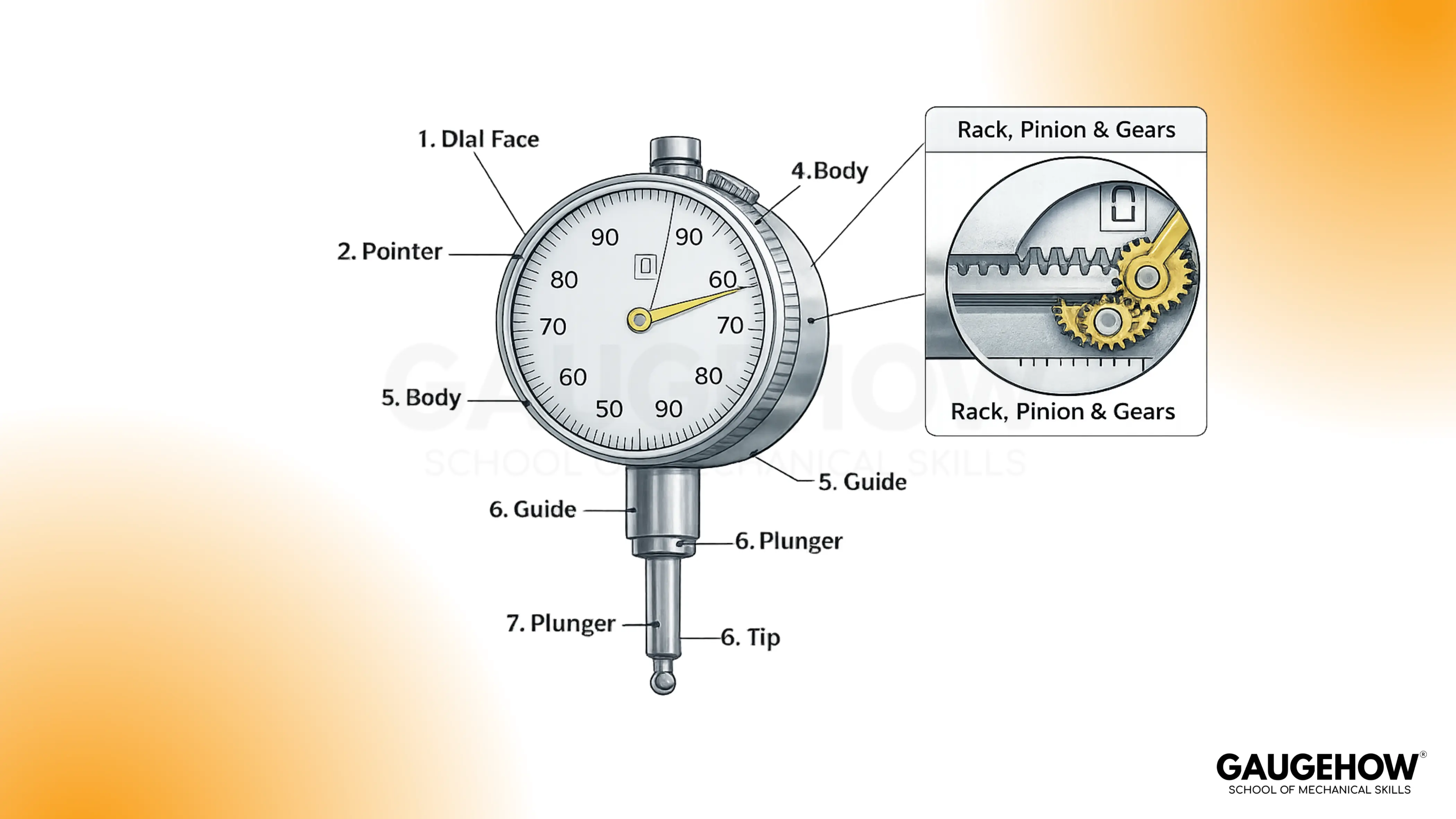
Below the tip, the plunger slides in a guide. Inside the body, the plunger carries a rack. Rack teeth engage a pinion. Gears rotate the pointer across the main dial. A small counter tracks full pointer revolutions.
Dial indicator parts
Dial indicator parts define repeatability more than the dial face does. Stable readings require smooth motion transfer and rigid mounting.
1. Contact tip: At the contact point, the tip touches the surface and defines where the peak is found. Tip wear or a rounded face lets it slide, so the high spot shifts.
2. Plunger: Under contact load, the plunger moves linearly and carries the displacement into the mechanism. Side-loading increases friction, so the plunger sticks and under-reads motion.
3. Guide bush: Along the travel path, the guide bush keeps the plunger aligned, and alignment protects repeatability. Wear in the guide adds tilt, so cosine error increases and values drift.
4. Return spring: Spring force keeps the tip seated, and a stable seat keeps the rack engaged consistently. Weak spring force allows bounce, so peaks fluctuate and readings become noisy.
5. Rack: Inside the body, the rack converts plunger travel into gear input, and smooth tooth engagement keeps the pointer stable. Dirt on the teeth causes skipping or dragging, so the pointer jumps or lags.
6. Pinion: Backlash at the pinion controls what happens after reversal, and that matters because setup checks often change direction. Reversals near zero lose small motion first, so the pointer delays before it responds.
7. Gear train: Through the gear train, rotation is scaled into a readable pointer sweep, and tight engagement supports repeatable cycles. Delay appears when gears wear, so lost motion grows and return values disagree.
8. Bezel clamp: From the bezel clamp, the zero reference is locked, and a fixed zero makes drift visible during checks. Loose clamping lets the bezel slip, so repeatability breaks even if the part is stable.
9. Dial and pointer: With the dial and pointer, you read divisions reliably, and clear marks reduce operator variation. Low-contrast printing or glare increases the likelihood of misreading by a division, so small changes get masked.
10. Stem or lug mount: During mounting, the stem or lug transfers load into the stand, and rigidity keeps the contact angle consistent. Flex in the stack changes that angle, so the indicator under-reads displacement.
At the dial face, parallax is a reading error from viewing angle. Eye position is kept normal to the dial plane to reduce it.
Dial Indicator Working Principle
Dial indicator's working principle is contact comparison with mechanical conversion. The operation type is linear input and rotary output. Interacting parts include the plunger, rack, pinion, gear train, and pointer. That chain determines whether small motion transfers without loss.
Motion mapping uses a rack and pinion sequence. The plunger carries a rack, and the rack drives a pinion. Inside the body, the pinion drives a gear train. Rotation reaches the pointer and moves it over divisions.
During contact, the return spring keeps the rack engaged. Consistent preload keeps teeth seated. When direction reverses, backlash appears first. That slack delays pointer movement until gears re-seat.
Because the rack moves linearly, the pinion rotates. That rotation causes the pointer to sweep the dial.
Dial Indicator least count
Dial Indicator least count is the displacement represented by one dial division. Reading resolution is treated as “per division” on the main dial.
Least count is the displacement per one dial division. Division count comes from the dial face markings.
Least count = travel per one pointer revolution ÷ number of dial divisions. Travel per revolution is set by the internal gearing.
Items & Symbols Notes
Item | Symbol | What you read | Unit |
Dial divisions | N | Marks on the main dial | divisions |
Travel per revolution | T | Travel for one full pointer turn | mm |
Least count | LC | T ÷ N | mm/div |
Full revolutions | R | Small dial counter reading | mm |
Main dial divisions | D | Pointer divisions from zero | divisions |
Worked example
During setup, T is 1 mm per pointer revolution. Dial face marks show N = 100 divisions.
LC = T ÷ N = 1 mm ÷ 100. LC equals 0.01 mm per division.
Small counter shows R = 4 mm. That value represents full revolutions.
Main pointer shows D = 37 divisions. Fine motion equals 37 × 0.01 mm = 0.37 mm.
Total displacement equals 4.00 mm + 0.37 mm. Final reading equals 4.37 mm.
Under poor mounting, one division can be lost in flex. Repeatability is checked before trusting the number.
🔧 Trusted by 23,000+ Happy Learners
Industry-Ready Skills for Mechanical Engineers
Upskill with 40+ courses in Design/CAD, Simulation, FEA/CFD, Manufacturing, Robotics & Industry 4.0.
Reading errors and correction rules
Motion-line errors (Cosine and Backlash)
Cosine error occurs when contact is not along the motion line. Under-reading shows up as a smaller swing than expected.
Correction uses alignment to the motion direction. Contact axis is set parallel to the displacement axis.
Backlash error shows up after a reversal near zero. Pointer delay is seen before motion appears on the scale.
Correction uses one-direction approach. Final readings are taken after approaching from the same side.
Viewing errors (Parallax)
Parallax error shows up as pointer misplacement by eye angle. A one-division shift can occur on fine scales.
Correction uses straight-on viewing. Eye position is centered above the pointer tip.
Reference errors (Zero shift)
Zero shift shows up as a changed reference after cycling. A stable tool returns to the same zero.
Correction uses preload and seating. Contact is compressed 1 mm to 2 mm before zero is set.
Corrected reading example (with zero error)
After zeroing, the pointer rests at +2 divisions with no load. Least count is 0.01 mm per division.
Observed reading is 4.37 mm. Zero error is +2 × 0.01 mm = +0.02 mm.
Corrected reading equals observed minus zero error. Corrected displacement equals 4.37 mm − 0.02 mm = 4.35 mm.
Dial Gauge Types
Selection uses contact direction, access, and travel requirement. Mounting constraints usually decide the type first.
1. Plunger indicator
It fits axial contact on open surfaces. Common travel is 10 mm with 0.01 mm divisions. With side loading, friction rises and return can lag.
2. Lever test indicator
It fits tight access with side contact. Small travel suits edge finding and small features. At steep angles, indicated motion changes with lever geometry.
3. Long-stroke plunger
It fits fixture travel checks and larger movements. Extended travel increases spring force during compression. On soft materials, a higher force can mark the surface and shift readings.
4. Digital indicator
It fits fast reading and data capture. Display resolution can be 0.01 mm or finer. With a low battery, availability drops, and zero stability can be interrupted.
Range band selection
Access condition | Contact direction | Travel band | Main risk |
Open face | Axial | 0 mm to 10 mm | Cosine error from angled mounting |
Tight pocket | Side | under 1 mm | Angle sensitivity and stylus slip |
Fixture sweep | Axial | 0 mm to 30 mm | Higher force and mount flex |
Logging needed | Axial | 0 mm to 12.5 mm | Interrupted zero from handling |
Choosing and Using a Dial Indicator
The 3–6 step workflow you can repeat
A good result is mostly process, not talent.
Mount the indicator on a rigid base (mag base or stand), keeping arms short and joints locked.
Align the plunger axis as parallel as possible to the motion you want to measure.
Preload the tip into the surface by a consistent amount so the rack stays engaged.
Zero by rotating the bezel so the pointer sits at zero after preload.
Sweep the feature slowly (rotate the shaft or traverse the surface) and avoid direction reversals mid-reading.
Record peak high, peak low, and peak-to-peak, plus the approach direction you used.
Dial Indicator vs Dial Test Indicator vs Dial Gauge
One of the most asked queries that every engineer clicks is: Dial Indicator vs Dial Test Indicator vs Dial Gauge: It is mainly about contact style and what motion is being amplified, not about “accuracy.”
A dial indicator is typically a plunger-style comparator that measures displacement along the plunger axis. A dial test indicator uses a lever and stylus to reach tight features and indicate small deviations with side contact.
Dial gauge is a common shop name used interchangeably with dial indicator, although people sometimes use it as an umbrella term for both styles.
FAQ
1. How is zero set correctly?
Zero is set after preload is applied. Preload is kept constant across checks.
2. Why do readings change between repeated sweeps?
Mount flex and side load change the motion path. Backlash and sticking also change return behavior.
3. When is a lever test indicator chosen over a plunger type?
A lever type is chosen for restricted access. Side contact becomes easier without forcing plunger angle.
4. What does the small dial mean compared with the main dial?
The small dial tracks full pointer revolutions. The main dial shows fine divisions within one revolution.
5. How is least count different from accuracy?
Least count is the smallest division you can read. Accuracy is the closeness of the reading to true displacement.


