How to use a Dial Indicator: Setup, Zeroing, Calibration

To read a dial indicator, preload the tip, set the bezel to zero, then count needle divisions and full turns. The large hand shows the fine units, and the revolution counter shows full turns. Your result is the difference between the highest and lowest reading.”
A part is on limit, and your reading decides whether to accept or rework. Most wrong readings come from the setup chain, not the dial face.
Once you can How To Read A Dial Indicator with a repeatable routine and two quick checks, the needle stops feeling “interpretive” and starts feeling reliable.
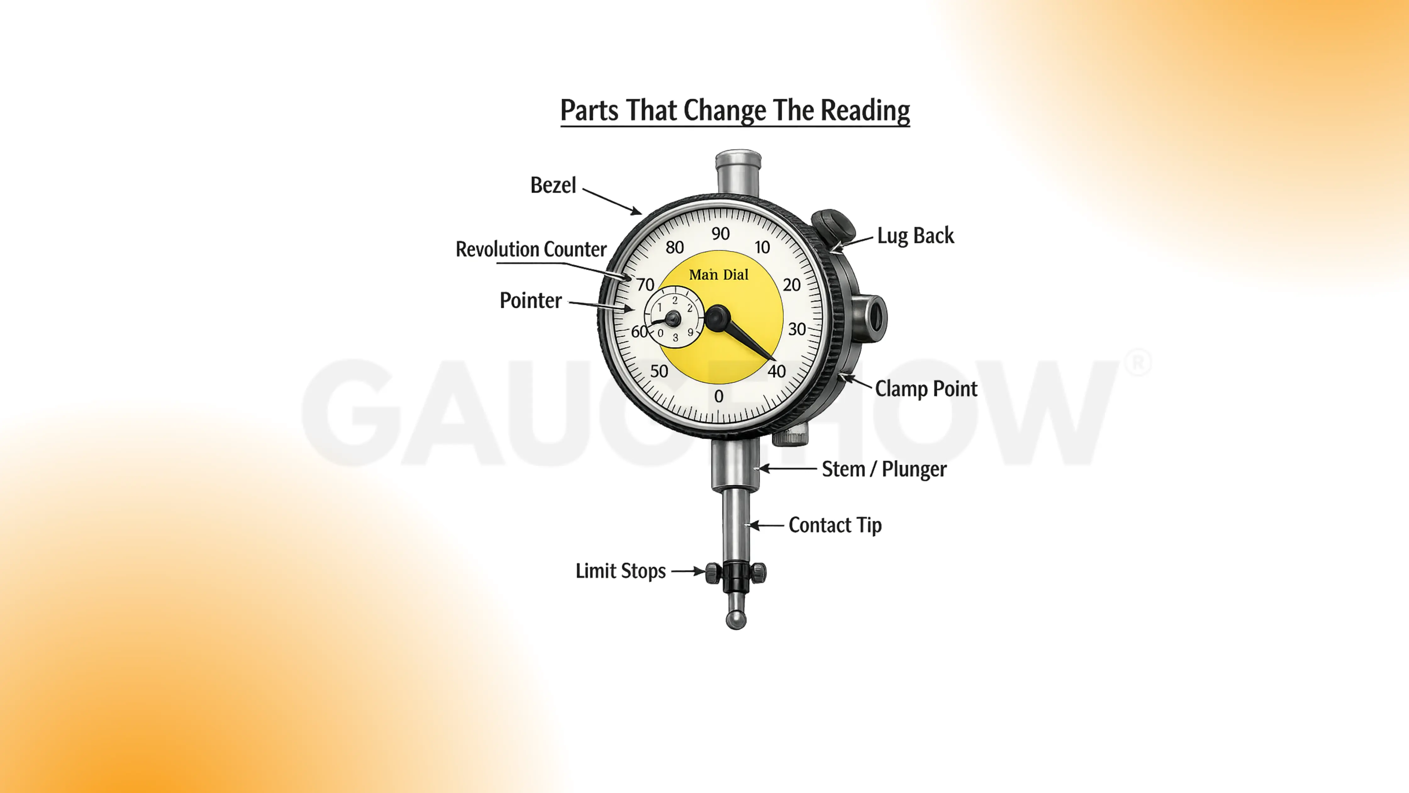
Parts And Scales
Dial Indicator parts are listed below in the diagram:
Any looseness in the clamp chain shows up as a wandering zero.
1. Bezel
The bezel defines your zero for this measurement. If it rotates, your reference moved, so the result shifts. Tap the bezel once after zeroing, then confirm that zero stayed.
2. Main dial and pointer
The pointer is the fine readout you count in divisions. Parallax changes the division you “see” because your eye moved. Read straight-on, then re-check from the same viewing position.
3. Revolution counter
The counter tracks full turns during larger travel. Missing a full turn causes a big error that looks believable. Check the counter before you write down any final number.
4. Stem or lug back
This mount is the first stiffness link in the setup chain. Any looseness here becomes motion, and the dial reports it. Press the stand lightly, and watch if the needle responds.
5. Plunger and contact tip
This is where surface contact becomes spindle travel. Side load creates sticking, so readings depend on the approach direction. Move the spindle slowly by hand, and feel for smooth return.
6. Limit stops
Limit stops protect the indicator from over-travel damage. Near the end of travel, return can degrade, so readings stop repeating. Keep preload away from the ends, and reposition if needed.
Bench habit: If the stand can flex, the dial will “measure” that flex.
Set Up and Zero Routine
A stable reading is built before you look at the numbers.
Clean the contact tip and the surface. Dirt is a spacer.
Mount rigid. Short arms, tight joints, solid base contact.
Square the contact direction. Keep the plunger close to the true motion direction.
Preload about one turn. Enough to keep spring tension, not near the end travel.
Set zero with the bezel. Choose your reference point and commit to it.
Sweep slowly. Fast sweeps hide stick-slip and bounce.
Re-seat and verify. Lift off, touch again, confirm the reading repeats.
Verification checks
Zero return check: Touch, release, touch again. Zero should return within one division.
Repeatability check: Take 3 touches at the same point. Spread should stay within one division.
Approach direction rule: Approach the final reading from the same direction each time so backlash effects do not sneak in.
If the re-seat check fails, stop and fix the setup. Do not “average” your way out.
The Formula for Reading a Dial Indicator
The dial is just a counted movement.
Total movement = (divisions × value per division) + (full turns × travel per turn)
Read the divisions first, then add any full turns from the counter. Report results as deviation from zero, not as a “size.”
A missing plus or minus causes more confusion than the dial itself.
Resolution And Least Count
Resolution is the smallest increment the dial shows. Least count, in practical use, is the smallest increment you can read consistently without guessing.
A simple selection rule usually holds: pick an indicator where one division is comfortably smaller than the tolerance decision you’re trying to make. A stiff setup matters even more than a finer dial when the bench is real.
Choose the stand first, then choose the indicator. A delicate indicator on a flexible arm wastes time.
Reading A Dial Indicator In MM
Treat the reading like a lab note.
Assume a metric dial where:
0.01 mm per division on the main dial
1.00 mm per full turn (common on many metric indicators)
Example:
Zero point: bezel set at contact on the reference surface
During the sweep: max is +18 divisions, min is –07 divisions
Convert each point:
Max = +18 × 0.01 mm = +0.18 mm
Min = –07 × 0.01 mm = –0.07 mm
Keep the numbers with signs. It prevents a wrong subtraction later.
If you cross full turns, pause, and confirm the counter before you record anything.
Reading A Dial Indicator In Inches
Again, write it like a note you can audit later.
Assume an inch dial where:
0.001 in per division on the main dial
0.100 in per full turn (common on many inch indicators)
Example:
Zero point: bezel set on your reference
During the sweep: max is +22 divisions, min is 05 divisions
Convert each point:
Max = +22 × 0.001 in = +0.022 in
Min = –05 × 0.001 in = –0.005 in
If your eye position changes, re-read once. Parallax is quiet.
🔧 Trusted by 23,000+ Happy Learners
Industry-Ready Skills for Mechanical Engineers
Upskill with 40+ courses in Design/CAD, Simulation, FEA/CFD, Manufacturing, Robotics & Industry 4.0.
Dial Indicator vs Dial Test Indicator
Choosing the wrong tool creates “mystery readings” that are actually geometry problems. Dial Indicator vs Dial Test Indicator is mainly a contact-direction decision, along with travel range.
Tool | Best Jobs | Contact Style | Typical Mistake | Quick Rule |
Dial indicator | General travel checks, runout checks, and longer movement | Straight push | Side-loading the plunger | Use it when motion is mostly straight-in/out |
Dial test indicator | Sweeping faces, bores, and tight access | Side contact, lever style | Treating it like a plunger indicator | Use it when you must sweep across a surface |
Plain-language rules that hold up on the bench:
Dial indicator: Straight push, longer travel, general runout, and travel checks.
Dial test indicator: Side contact, small travel, sweeping faces, bores, tight access.
If the setup forces a sideways touch, switch tools rather than forcing the plunger.
Runout, TIR, And What To Record
Runout readings only mean something if the setup is honest. Clamp rigidity, contact angle, and approach direction control more errors than the dial face.
TIR definition
TIR (Total Indicator Reading) = highest reading minus lowest reading during one sweep or one rotation.
After you set zero, you sweep once, capture max and min, then subtract.
Worked TIR example (metric, 0.01 mm per division)
Zero point: bezel set at the starting contact point
Max reading: +16 divisions
Min reading: –06 divisions
Convert:
Max = +16 × 0.01 mm = +0.16 mm
Min = –06 × 0.01 mm = –0.06 mm
Subtraction: +0.16 − (−0.06) = 0.22 mm
Reported TIR: 0.22 mm TIR
Worked TIR example (inch, 0.001 in per division)
Zero point: bezel set at the starting contact point
Max reading: +19 divisions
Min reading: –04 divisions
Convert:
Max = +19 × 0.001 in = +0.019 in
Min = –04 × 0.001 in = –0.004 in
Subtraction: +0.019 − (−0.004) = 0.023 in
Reported TIR: 0.023 in TIR
What to record
Item | Meaning | Example entry |
Location | Where the tip touched | 10 mm from end, mid-height |
Setup | How the part was supported | V-blocks, tailstock support |
Preload | How much spring compression | ~1 turn |
Max / Min | Extremes during sweep | +0.019 / –0.004 |
Reported TIR | Max minus min | 0.023 in |
Verification | Re-seat check result | Returned within 1 division |
Record max and min, not just the final TIR. It helps you spot drift.
Dial Indicator Calibration
A full calibration is a controlled metrology activity. A bench verification tells you whether the indicator is behaving today. Dial Indicator Calibration at the bench is about smooth motion, consistent return, and sensible agreement with a known stack.
Practical bench verification
Mount the indicator rigidly over a stable base.
Zero on the base surface with light preload.
Insert a known step (block stack or mic head change).
Record the indicator reading.
Repeat at several points across the travel you actually use.
Approach each point from the same direction, then repeat once from the opposite direction to sense “sticky” behavior.
Re-seat at one point and confirm it returns within one division.
Record item | Role | Example entry |
Reference step | Your known change | 0.50 mm |
Indicator reading | What it showed | 0.49 mm |
Difference | What would you correct | −0.01 mm |
Direction | Helps spot stick-slip | up / down |
Return check | Confirms stability | within 1 division |
If forward and reverse feel different, stop trusting the last digit.
Common Mistakes When Reading Dial Indicators
Most bad readings come from one small setup detail. If the value surprises you, reset once, then prove the setup is behaving before you trust the number.
Mistake | Impact | Bench sign | Fix habit |
Return-to-zero drift | Your “zero” moves, so every result is polluted | Touch → lift → touch again. Zero doesn’t come back within 1 division | Shorten the arm, tighten joints, use the same preload, and the same approach |
Cosine error | You under-read variation, so runout looks better than it is | Re-angle the tip slightly and re-sweep. The number changes without the part changing | Aim near the square, lock the stand, then touch the part |
Stick-slip / hysteresis | Readings depend on direction, so max/min becomes unreliable | Approach the same point from both directions. The two readings don’t match | Reduce side-load, slow the sweep, approach final readings from one direction |
Dirt/burr/oil film | You measure contamination, not the surface | Wipe tip and track, then re-seat. The value drops | Clean before zeroing, avoid damaged edges, choose a clean contact track |
FAQs
1) How much preload should you use before zeroing?
About one turn is a practical starting point on many dials. The exact number matters less than consistency. Preload enough to keep spring tension, then confirm you still have travel in both directions.
2) Why does the reading change when you reposition the stand?
That change is usually geometry or rigidity. A new contact angle introduces cosine error, and a longer arm introduces flex. Square the contact, shorten the setup, then repeat the sweep.
3) What does the revolution counter actually do?
It prevents you from losing track of full turns of the main pointer. Use it during longer sweeps so total travel remains auditable.
4) How do you know your runout reading is trustworthy?
Pass the re-seat check and record max and min. If the zero return shifts more than one division, fix the setup before you trust any TIR value.
5) When should you verify the indicator on a reference?
After a drop, after a sticky feel, after a surprising reading, or when a return within one division fails. A quick block or mic-head check is faster than chasing bad conclusions on parts.


