Gear Tooth Vernier Caliper: Diagram, Formula & Least Count

A gear tooth vernier is a metrology tool used to measure chordal thickness at the pitch circle by controlling the measuring depth first and the tooth thickness second.
In production and QA, the real problem is simple: you need a fast, repeatable way to catch tooth-thickness drift before it turns into noise, fit issues, scrap, or rework. That drift often appears when tooling wears, heat treat moves a dimension, or finishing changes flank contact.
Conventional quick checks struggle because tooth thickness changes with measurement height, and “across the tooth” contact is easy to place inconsistently on chamfers, burrs, and wear.
Gear Tooth Vernier Caliper solves that by forcing a controlled depth setting, so readings are comparable tooth-to-tooth and part-to-part, which protects throughput and reduces escapes.
Selection snapshot
Used for | Benefits | Limits | Best practice |
In-process thickness trending | Fast, depth-controlled readings | Not ideal for tight final acceptance | Measure 5 teeth and log spread |
Incoming screening | Quick pass/fail against target | Operator technique drives results | Standardize force and seating |
Troubleshooting drift | Identifies thickness movement early | Not a full geometry audit | Pair with a reference method when needed |
What is Gear Tooth Vernier Caliper
A gear tooth vernier caliper measures tooth thickness at a defined depth from the tooth tip, so the thickness value is tied to a consistent chord location rather than a “best guess” contact point.
The instrument does this with two perpendicular slides: one sets the depth, the other reads the thickness at that depth.
This tool is used for spur gear tooth thickness checks when access is good and the goal is screening, trending, or process control.
It becomes less reliable when teeth are very small, flanks are badly worn, or the geometry demands a higher-precision acceptance method.
Gear Tooth Vernier Working Principle
The mechanism is a two-stage control: you set the measuring depth with the vertical slide, then you measure the thickness with the horizontal jaws at that exact depth.
The depth setting is the control that stabilizes the measurand across different teeth.
In Gear Tooth Vernier Working Principle, depth comes first because tooth thickness varies along the flank.
When the depth is correct, the jaws land on the intended portion of the tooth, and repeat readings cluster tightly. When the depth is wrong, the jaws contact a different flank height, so the reading shifts even if the scale is perfect.
Gear Tooth Vernier Diagram
The Diagram of Gear Tooth Vernier Diagram is given below with labeled parts:
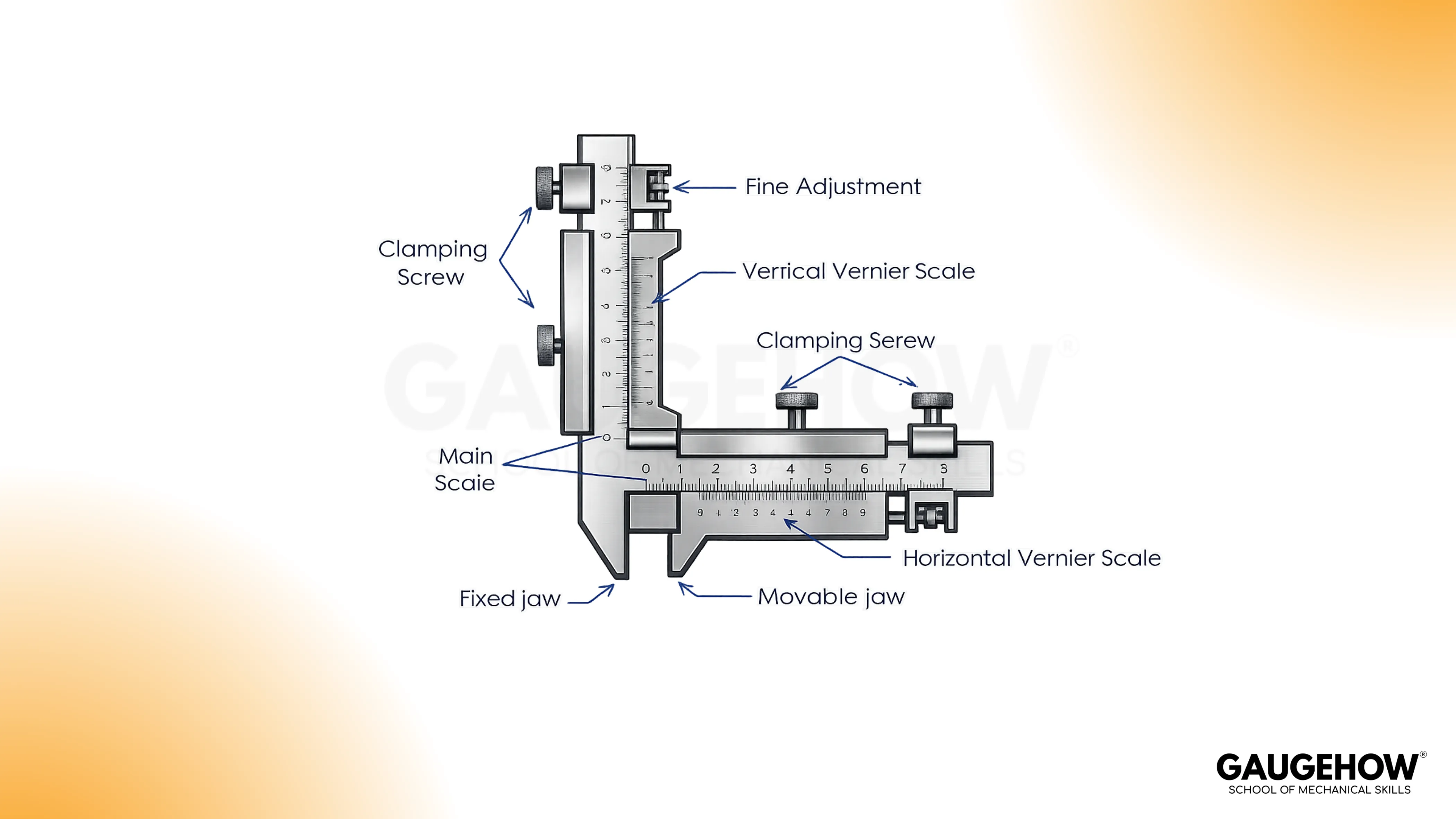
Component | Role | Measurement impact |
Main scale | Primary reference for each slide | Damaged markings slow reading and increase operator error |
Vernier scale | Fine interpolation between divisions | Poor alignment habits create consistent bias |
Fixed jaw | Stable flank reference point | Jaw wear shifts contact location and reduces repeatability |
Movable jaw set (thickness) | Contact both flanks at set depth | Rounded edges ride on chamfers and read high/low unpredictably |
Movable depth stop | Establishes the depth setting | Drift here makes every thickness value unreliable |
Lock screws/nuts | Freeze position without a hand load | Over-tightening can push contact and change the reading |
Fine adjustment | Controlled closing motion | Reduces “overshoot” and stabilizes contact pressure |
Bevel edge | Helps flank seating on narrow teeth | Burrs here cause slipping and scattered readings |
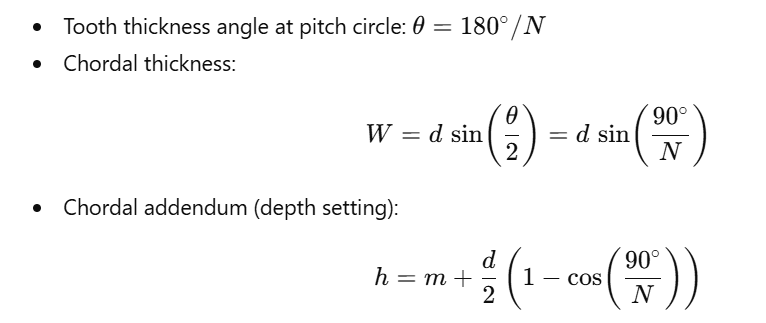
Gear Tooth Vernier Formula
Use Gear Tooth Vernier Formula as setup data for the depth setting and the target chord value.
The equations below are for standard spur gears where the tooth thickness at the pitch circle corresponds to half the circular pitch.
Variables
Symbol | Meaning | Notes |
N | Number of teeth | Whole number |
m | Module | mm (or convert from DP) |
d | Pitch circle diameter | ( d = mN ) |
h | Chordal addendum (depth setting) | Depth from tooth tip to chord line |
W | Chordal thickness | Thickness read at the set depth |
Equations
Worked example
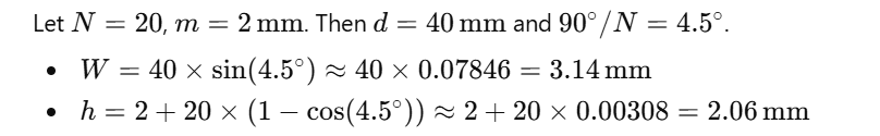
Setup implication: if the depth setting h is off, contact shifts along the flank, so W becomes false even when the jaws feel "seated."
Gear Tooth Vernier Least Count
Least count must be treated as a control knob, not a spec line, because it influences what variation you can actually trust on the floor.
Gear Tooth Vernier Least Count only tells you the resolution. Decision quality comes from separating resolution, repeatability, and accuracy.
Control block
Control | Meaning in practice | Simple field metric |
Resolution | The smallest step the instrument can display | Least count value |
Repeatability | How tightly your readings cluster | Spread across 5 teeth |
Accuracy | Agreement to spec or a reference method | Difference to target or reference |
Least count calculation (analog vernier principle)
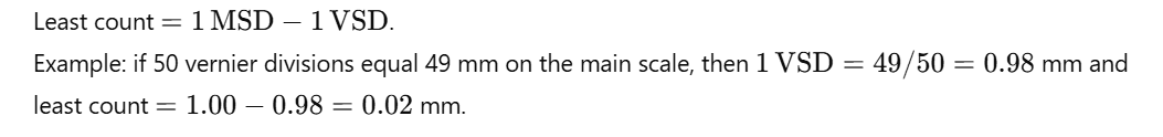
Field rule: If the spread across 5 teeth is larger than 2–3 least-count ticks, fix seating, force, or flank condition before trusting the average.
🔧 Trusted by 23,000+ Happy Learners
Industry-Ready Skills for Mechanical Engineers
Upskill with 40+ courses in Design/CAD, Simulation, FEA/CFD, Manufacturing, Robotics & Industry 4.0.
Testable Measurement Procedure
This procedure is written so an inspector can execute it, audit it, and get similar results across operators.
1. Prepare the tooth flanks
Wipe the flanks clean and remove burrs or sharp raised edges. Burrs don’t just “get in the way.” They shift where the jaw actually lands, so the contact height changes and the thickness reading moves even when your depth setting is correct.
2. Stabilize the instrument baseline
Close the jaws gently and confirm zero, then slide both movements through a short range to feel for stickiness. A sticky slide makes you apply extra force without noticing, and that force changes seating on the flank.
3. Set the depth setting
Set the vertical depth to your calculated value and lock it with a controlled touch. Treat this as the control that defines where on the tooth you are measuring. If this step is wrong, every thickness number after it can look consistent and still be wrong.
4. Seat the jaws on true flanks
Bring the horizontal jaws onto both flanks at the set depth. Avoid resting on chamfers, rounded tips, or worn shiny paths. If the tool “wants to climb” toward the tip, you are not seated on stable flank contact.
5. Control measuring feel
Close until you feel firm contact, then stop. Don’t squeeze for confidence. Extra force can shift the contact point up the flank, so the reading changes because the geometry changed, not because the tooth is different.
6. Lock without pushing the contact
Hold the tool steady at contact and apply the lock lightly. Over-tightening can nudge the jaw position and quietly bias the number. If your reading changes when you lock, your locking technique is influencing the result.
7. Repeat across multiple teeth
Measure at least five teeth spaced around the gear. Record each value and the spread between the highest and lowest. A tight spread is evidence of stable technique and seating. A wide spread is a control problem, even if the average looks “on spec.”
8. Compare using one method rule
Compare your average and your spread against your acceptance plan. Don’t switch methods mid-check to “confirm” a number unless that is part of your documented process, because method mixing creates false disagreement and hides the real cause of variation.
Measurement Quality Gate And Tool Choice
A reliable measurement is the result of controlled contact, controlled depth, and controlled technique. The key quality wedge is understanding the difference between resolution, repeatability, and accuracy, because they fail for different reasons.
Resolution is a scale property.
Repeatability is an operator and contact property.
Accuracy is agreement to the drawing or a reference method, and it only matters after repeatability is stable.
Common symptom control
Symptom | Cause | Correction | Prevention |
Readings consistently high | Contact too close to tooth tip | Re-seat, reduce force, confirm depth | Standard seating feel |
Readings consistently low | Contact shifted down the flank | Reset depth, avoid worn zones | Inspect flanks before measuring |
Large tooth-to-tooth spread | Burrs, runout, inconsistent force | Deburr, increase sample teeth | Log every check |
Operator-to-operator mismatch | Different seating angles and pressure | Align technique and sequence | One method sheet per job |
Operator controls that stabilize readings
Use the same hand position and closing feel every time, because force changes contact height.
Lock gently while holding position, because locking can push the jaws.
Measure multiple teeth and record spread, because one reading is not evidence of stability.
Keep flanks clean, because burrs and oil films create false seating.
FAQs
1. What does a gear tooth vernier caliper measure exactly?
It measures chordal tooth thickness at a controlled depth, typically aligned to the pitch circle intent. The depth setting defines the measurement location, so thickness readings are comparable across teeth and parts.
2. Why do I set the depth first before measuring thickness?
Because tooth thickness changes along the flank. If the depth is wrong, the jaws contact a different height and the reading shifts. Depth control locks the measurement location before you read thickness.
3. What causes inconsistent readings tooth to tooth?
Most scatter comes from seating differences: burrs, chamfers, wear patches, or changing hand force. Clean flanks, standardize measuring feel, and record five-tooth spread. Tight spread is your reliability indicator.
4. How do I know if my least count is good enough for this job?
Least count is the only resolution. Your real limit is repeatability. If the spread across five teeth is more than two to three least-count ticks, fix the technique or seating before trusting the average result.
5. When should I avoid using a gear tooth vernier caliper?
Avoid it for tight acceptance decisions, very small teeth, poor flank access, or heavy wear. Use it for screening and trending, then confirm with a controlled-contact method when risk is high.


