How to Use a Dial Bore Gauge to Measure Cylinder Bores

A dial bore gauge is a comparator used to check internal diameters such as cylinder bores. You set it to a known size, place it in the bore, rock it to the reversal point, and read the deviation on the dial.
How to use a dial bore gauge comes down to consistent zeroing and consistent rocking.
Role at bench | Output you write down | Acceptance rule | Proof check |
Cylinder condition check | Six-point deviation grid | Taper and ovality stay within service limit | Master returns within 1 small division |
Housing fit control | Deviation at the fit zone | Clearance band stays in spec | Same point repeats within 1–2 divisions |
Process verification | Trend of deviation across parts | Drift stays inside control plan | Zero is rechecked at set intervals |
Most measurement errors happen before the reading. Dirt, wrong contact stack, and an inconsistent rocking angle create numbers that look precise but do not repeat.
The sections below keep the flow predictable: what the tool is, what the parts do, how the mechanism responds, how you set it, how you measure a cylinder bore, and how you calculate least count and read the dial.
What Is a Dial Bore Gauge?
A dial bore gauge, also known as a dial bore gauge or bore gauge, is a precision instrument used to check the size and form of an internal diameter. It is commonly used in engine work, machining, and inspection because it shows small deviations quickly.
This tool does not directly “tell you the diameter” unless you first set it to a reference size. After setting, the dial shows how far the bore differs from that reference. That difference is the value you care about when checking wear, taper, and out-of-round.
Dial Bore Gauge Diagram And Parts
A dial bore gauge diagram is given below:
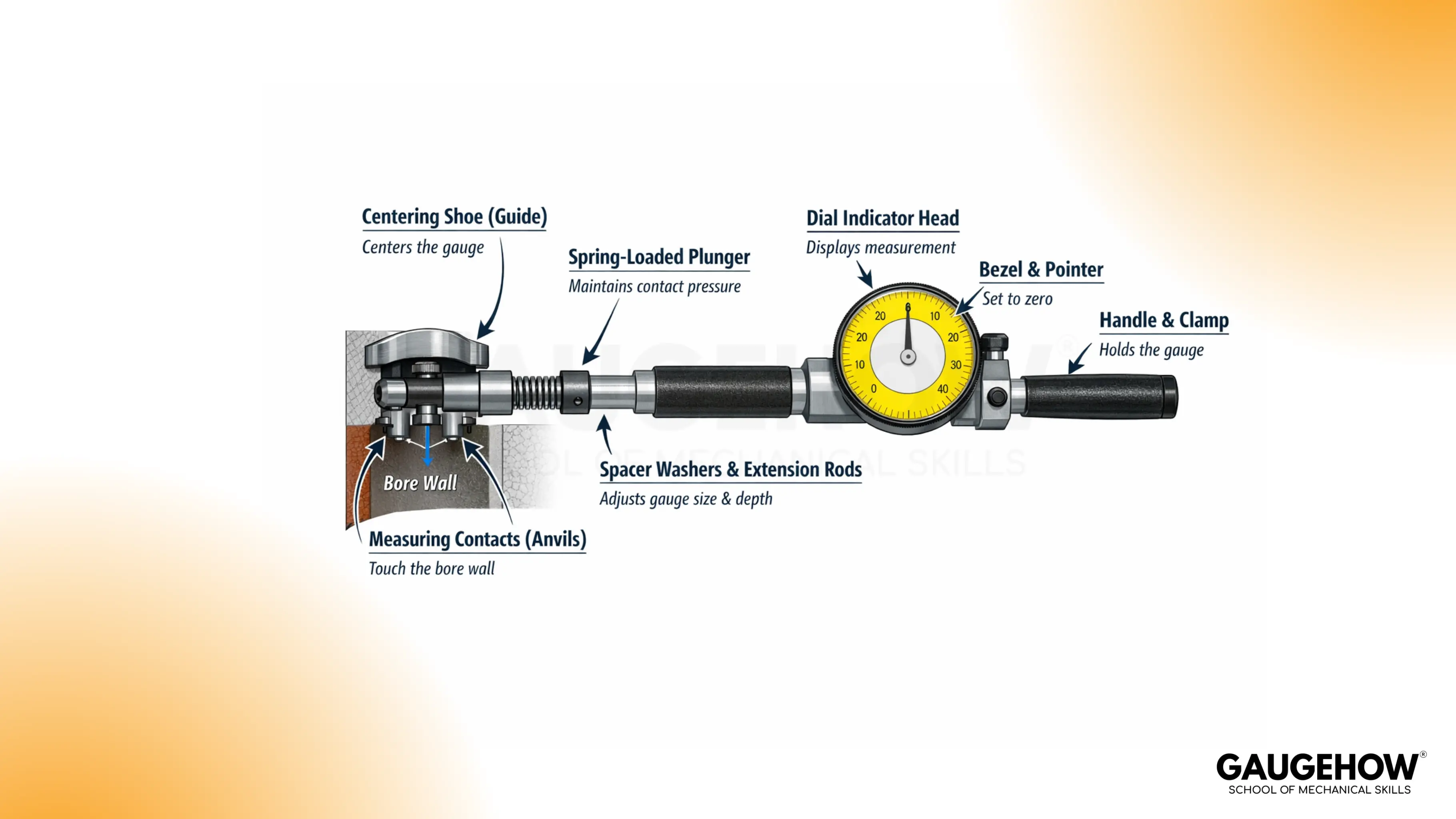
Measuring contacts (anvils): Touch the bore wall and define the measuring diameter.
Spring-loaded plunger: Maintains contact pressure and allows small displacement.
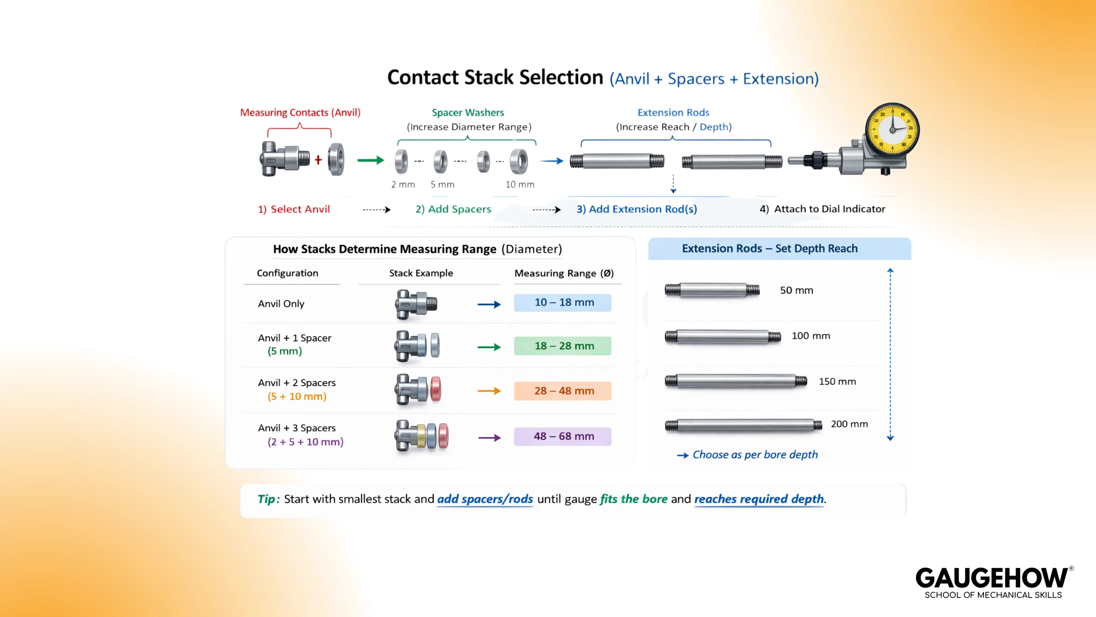
Spacer washers and extension rods: Adjust the gauge to the desired diameter and reach depth.
Centering shoe or guide (on some sets): Helps the gauge sit more consistently in the bore.
Dial indicator head: Displays displacement as needle rotation on the dial face.
Bezel and pointer: Let you set the dial to zero at the reference size.
Handle and clamp: Hold alignment and keep the indicator rigid to the body.
Working Principle Of A Dial Bore Gauge
The operation is analog. Small movement at the contacts becomes a visible needle movement on the dial.
Inside the bore, the contacts sit on opposite sides of the diameter. When the bore is larger than the reference, the plunger travel changes, and the indicator needle shifts away from zero.
When the bore is smaller, the needle shifts the other way. The sign depends on how the indicator is mounted and how you define your “plus” direction, so the important habit is consistency.
Repeatability comes from one event: the reversal point during rocking. As you rock the tool through the bore axis, the needle reaches an extreme value and then reverses direction. That extreme is the truly aligned reading. Any reading taken before that point is a cosine error.
Bore Dial Gauge Least Count and Reading
The bore dial gauge least count is the smallest change in size the dial can display per one division. It depends on the dial scale and the mechanism ratio inside the indicator.
Least Count = (Value represented by one full revolution) / (Number of divisions on the dial)
A common dial has 100 divisions per revolution, but the value per revolution depends on the indicator. Many sets are supplied with either 0.01 mm per division or 0.001 in per division indicators. The dial face marking is the source of truth.
Example 1: setup → reading → math → decision
Setup: master is 80.000 mm, dial face is 0.01 mm per division.
Reading: extreme shows +3 divisions.
Math: deviation = 3 × 0.01 = +0.03 mm, so bore = 80.030 mm.
Decision: if the clearance plan allows +0.03 mm, accept. If not, correct the process.
Example 2: zero error → correction → decision
Setup: master is set, but the pointer sits at +1 division in the master.
Reading: a point shows +4 divisions at the extreme.
Math: corrected deviation = 4 − 1 = +3 divisions = +0.03 mm.
Decision: use corrected values for taper and ovality, not the raw dial numbers.
Example 3: repeatability beats resolution in practice
Setup: dial shows 0.001 in divisions, but the operator repeats the same point with a spread of 0.003 in.
Reading: the spread is larger than one division.
Decision: improve seating, rocking speed, and zero checks before trusting fine divisions.
When the dial bore gauge is handled with a proof gate, the grid becomes a decision tool, not a guess.
Difference Between Bore Gauge and Telescoping Gauge
Tool role | Strength | Limitation | Best choice when |
Dial-type bore comparator | Shows deviation live | Needs a reference and a stable technique | Taper or ovality decisions matter |
Telescoping gauge | Simple transfer tool | Depends heavily on feel | Quick checks are acceptable |
3-point bore micrometer | Good centering behavior | Higher cost and limited range of steps | Direct ID measurement is required |
🔧 Trusted by 23,000+ Happy Learners
Industry-Ready Skills for Mechanical Engineers
Upskill with 40+ courses in Design/CAD, Simulation, FEA/CFD, Manufacturing, Robotics & Industry 4.0.
Types And Setup Of A Dial Bore Gauge
Common configurations used in shops:
Two-point contact dial bore gauge: Uses opposing contacts with a spring-loaded plunger and a dial indicator. This is the typical set used for cylinders.
Three-point internal micrometer style: Uses three contacts for self-centering. It is excellent for size checks, but it is a different tool style from the dial-indicator set.
Short-reach vs deep-reach bodies: Reach affects feel. Deeper setups need more care to keep the tool square.
The setup is mainly two decisions: diameter range and reference method.
Select the contact stack. Choose anvils and spacers that put the tool near the nominal bore size. The goal is to keep the plunger in a mid-travel region so it can move in both directions.
Choose a reference. A micrometer set to nominal is common. A setting ring or master bore can be faster when you repeat the same size all day.
Before measuring parts, confirm the feel. The tool should spring smoothly, and the needle should move without sticking.
Measuring Cylinder Bores Step by Step
Cylinder bores are not judged at one height and one direction. Wear patterns are directional, and taper is height-based, so the measurement plan must capture both.
A practical recording grid is shown below. It keeps your notes usable after you walk away from the bench.
Height in bore | 0° axis (thrust) | 90° axis | Notes |
Top (near ring travel) | - | - | - |
Middle | - | - | - |
Bottom | - | - | - |
Use this sequence:
Prepare the bore. Clean it and remove oil film that can changethe contact feel. A light wipe is usually enough.
Set to nominal. Use your reference method and bring the needle to zero at the reversal point in the reference.
Insert and align. Hold the tool near the axis you want to measure. Keep the body square to the bore.
Rock and capture the reversal point. Sweep through the centerline slowly until the needle peaks and reverses. That peak reading is the value you record.
Repeat at each grid point. Move to the next height, then rotate ninety degrees for the second axis.
Check repeatability. Recheck one earlier point. A drift usually means alignment or contact pressure changed.
For repeatable cylinder work, the most important habit in how to use a dial bore gauge is taking every reading at the same reversal point, not at a “convenient” needle position.
Interpreting taper: Compare top, middle, and bottom readings on the same axis. A difference across heights is taper.
Interpreting out-of-round: Compare 0° and 90° readings at the same height. A difference across axes is ovality.
If your numbers do not repeat, stop and verify zero again. A fast re-zero prevents chasing a false taper pattern.
Dial Bore Gauge Uses & Errors
A dial bore gauge is commonly used for:
Checking engine cylinder bores during rebuild and inspection.
Verifying machining results on bushings, bearing bores, and housings.
Comparing bores in production when fast deviation checks matter.
Confirming roundness changes after honing or boring operations.
Common errors and what to verify:
Dirty bore: Wipe and recheck. Dirt creates random spikes.
Wrong contact stack: Confirm you are near mid-travel, not bottomed out.
Misalignment: Square the body and take the reversal point, not a mid-sweep number.
Inconsistent rocking: Use the same sweep angle each time.
Zero drift: Re-zero after temperature change or after moving the setup.
Verification gate:
Zero the tool twice and confirm the same zero.
Measure one point three times and confirm the same reading.
Return to the reference and confirm the needle comes back to zero.
FAQ
How often should the master be rechecked during a long inspection run?
Recheck the master at the start, after any bump, and at fixed intervals. Heat from hands and the part shifts size slowly. If the pointer returns more than one small division away from zero, discard the grid and remeasure immediately.
Why does the needle peak then reverse?
Rocking changes the alignment until the contacts span the true diameter line. At that moment, the indicator reaches an extreme and then turns back. That extreme is the value to write down. Mid-swing values are projections, so they often mislead.
Can this method detect a tight spot near the top only?
Yes, but only if you map by height. Take readings at the top, middle, and bottom on two axes. A local tight spot appears as a higher deviation at one height only. Confirm by repeating the same depth and rocking direction.
What least count is good enough for cylinder work?
Least count sets dial resolution, not your real uncertainty. For many bores, technique repeatability is the limit. Choose a scale that lets you see change clearly, then prove you can repeat one point within one or two divisions every time.
Why do results differ between operators using the same tool?
Small differences in tilt and rocking speed change the projected diameter. Contact pressure also varies, so the extreme shifts slightly. A shared method fixes this: Same master, same direction through the extreme, and a return-to-zero check after mapping always together.


