How to Use a Digital Dial Indicator: Shop Workflow
A Digital Dial Indicator is a spring-loaded comparator that converts plunger travel into a numeric deviation.
You mount it rigidly, apply consistent preload, set a baseline, then sweep the feature and read repeatable peaks. The digits matter, but alignment, friction control, and baseline return matter more.
Stage | Starting Point | Operator Move | Gate Signal |
Stand posture | Base locked, joints snug | Light push on the arm | No visible flex, no rocking |
Contact preload | Tip just touches | Add a consistent preload | Smooth travel, no sticking feel |
Baseline set | Datum chosen | Set baseline, lift, and re-touch | Same baseline returns |
Sweep motion | Path planned | Sweep slowly, same path | Peak repeats by location |
Reading discipline | Peaks identified | Read peak-to-peak consistently | Similar results across passes |
Recording | Result needed | Record value plus location | Another operator can repeat |
Reset discipline | Setup changed | Re-touch the datum | Baseline holds after remount |
In day-to-day shop work, an indicator is only as good as the structure holding it. So the stand, the contact angle, and the preload window decide whether the number represents the part or represents your setup.
That is why this page is built around a fixed routine and short mini workflows, not just definitions.
Most “bad readings” are not random. They come from predictable causes like side load, angle loss, end-of-travel behavior, and inconsistent baseline habits.
Once you treat those as controllable variables, the tool becomes boring in the best way: it repeats, and it stops wasting your time.
Stand Rigidity and Contact Mechanics: Digital Indicator Stand setup.
Digital indicator stand setup matters because the stand is your reference structure, so any flex gets added to the reading.
Keep the stem aligned with the motion line, and keep the contact direction consistent through the sweep. Short, stiff geometry usually beats long arms and extensions.
A practical way to judge stiffness is simple: lock the base, then push the arm lightly with one finger.
If the contact point visibly shifts, the stand is now part of the measurement. Tighten joints, shorten the reach, and move the base closer rather than increasing clamp force.
Tip geometry also changes behavior. A ball tip is forgiving on curved surfaces, but it can skid if you approach sideways. A flat tip can be stable on broad flats, but it punishes angle error.
Either way, approach straight, because a side approach loads the plunger and creates stick-slip.
Controls Map for ABS, INC, Origin, and Zero
Mode confusion is common, but the cure is consistent habits.
Treat “ABS” as an origin you return to.
Treat “INC” as a temporary working baseline for the current setup.
Along with that, use the same approach direction every time, because the plunger spring and friction behave differently when you reverse direction.
Control | Mode Behavior | Role | Best Use | Common Confusion |
ABS | Fixed origin retained by the instrument | Reference point | Repeating a known origin across jobs | Assuming ABS equals “true size.” |
INC | Relative to the current baseline | Working baseline | One setup, one datum, one sweep | Forgetting you moved the baseline |
Zero | Sets baseline at the current position | Quick baseline | Starting a sweep at a datum | Zeroing in on a burr or chip |
Origin set | Defines the “home” reference | Stable return point | Repeating checks across parts | Mixing origin with baseline mid-job |
Hold / data | Freezes or exports a value | Recording aid | Logging peaks or handoff | Using hold to hide unstable readings |
How to Use the Indicator in 7 Steps
A routine works because it removes improvisation. Follow these steps in order, and you will spend less time arguing with the setup and more time seeing real variation.
Step 1: Placement and approach
Place the stand so the stem travel matches the direction you care about. Approach the surface in a straight motion, because swinging in from the side adds friction before you even start reading.
Step 2: Preload window
Add enough preload to stay engaged through the motion, but avoid running near the end of travel. Mid-stroke behavior is usually smoother, so repeatability improves without you doing anything clever.
Step 3: Baseline set
Pick a datum point that makes sense for the job, then set the baseline. Lift off and re-touch the same point once. If the baseline does not return, correct the stand posture and contact direction before you sweep.
Step 4: Sweep discipline
Sweep slowly and follow the same path each pass. Speed changes the contact dynamics, so fast sweeps can create peaks that look real but shift between passes.
Step 5: Peak reading habits
Read peaks, not noise. Run the sweep twice and watch whether the peak location repeats, because a repeatable location is usually more meaningful than a single “nice number.”
Step 6: Recording and handoff
Write down the value definition and the location. When you hand results to someone else, your Digital Dial Indicator reading is only useful if the next operator can recreate the same datum, sweep path, and approach direction.
Step 7: Reset discipline
Any time you loosen the stand, change the part, or shift the base, re-touch the datum and confirm baseline return. That habit prevents drift from turning into wasted troubleshooting.
Application Cards for Common Jobs in PDf/Blog
These mini workflows are structured the same way, so you can execute quickly: posture, baseline, sweep path, and the cue that tells you the reading is trustworthy.
Runout on a Shaft Using TIR
Element | Practical Notes |
Stand posture | Stem radial to the shaft, shortest arm you can manage |
Baseline point | Choose the first touch point, then keep the same approach direction |
Sweep path | Rotate the spindle slowly through 360° |
Good reading cue | Peak location repeats each rotation, not just the peak value |
Flatness Sweep on a Surface Plate
Element | Practical Notes |
Stand posture | Height stand with stiff column, minimal overhang |
Baseline point | Set baseline on a clean reference spot, then avoid re-zero mid-sweep |
Sweep path | Straight, consistent traverse lines across the surface |
Good reading cue | Similar results on repeat passes along the same line |
Hole Centering With an Indicator in the Spindle
Element | Practical Notes |
Stand posture | Indicator mounted rigidly in spindle, contact at the bore wall |
Baseline point | Start at a convenient clock position, then observe high and low |
Sweep path | Rotate spindle by hand and adjust table in X and Y |
Good reading cue | Peaks shrink symmetrically until the sweep is even around the bore |
Vise Jaw Parallelism Check
Element | Practical Notes |
Stand posture | Indicator in spindle or on a rigid arm, contact normal to the jaw |
Baseline point | Baseline at one end of the jaw, same approach direction |
Sweep path | Traverse along the jaw length at a constant height |
Good reading cue | Drift is smooth and repeatable, not jumpy or location-random |
Fixture Deflection Under Light Load
Element | Practical Notes |
Stand posture | Indicator on a stiff base, contact at the critical compliance point |
Baseline point | Baseline with no load, then apply load in the same direction |
Sweep path | Load on, load off, repeat in the same sequence |
Good reading cue | Load-on value repeats within a tight band across cycles |
Baseline Control: Zeroing a Digital Indicator
Zeroing a digital indicator is a baseline management step, not a measurement step, so it only works if the datum and the approach repeat.
Set the baseline on a clean, stable reference point, then lift and re-touch once before you commit to a sweep.
Baseline choice should match the job. A surface plate point works for bench sweeps, a master works for repeat checks, and a part datum works for alignment tasks.
What matters is consistency, because baseline drift creates “part movement” that is really setup movement.
Avoid three common traps: zeroing on a burr, zeroing at the end of travel, and zeroing while the plunger is side-loaded. Each one can produce a stable-looking number that does not repeat when the setup is disturbed.
🔧 Trusted by 23,000+ Happy Learners
Industry-Ready Skills for Mechanical Engineers
Upskill with 40+ courses in Design/CAD, Simulation, FEA/CFD, Manufacturing, Robotics & Industry 4.0.
Reading Errors
Angle loss and friction effects create believable numbers, so they waste time. Treat them like controllable variables, and you will spot them early.
Cosine Loss From Contact Angle
When the stem is not aligned with the motion you care about, you measure only a component of that motion. The display looks fine, but the value is reduced.
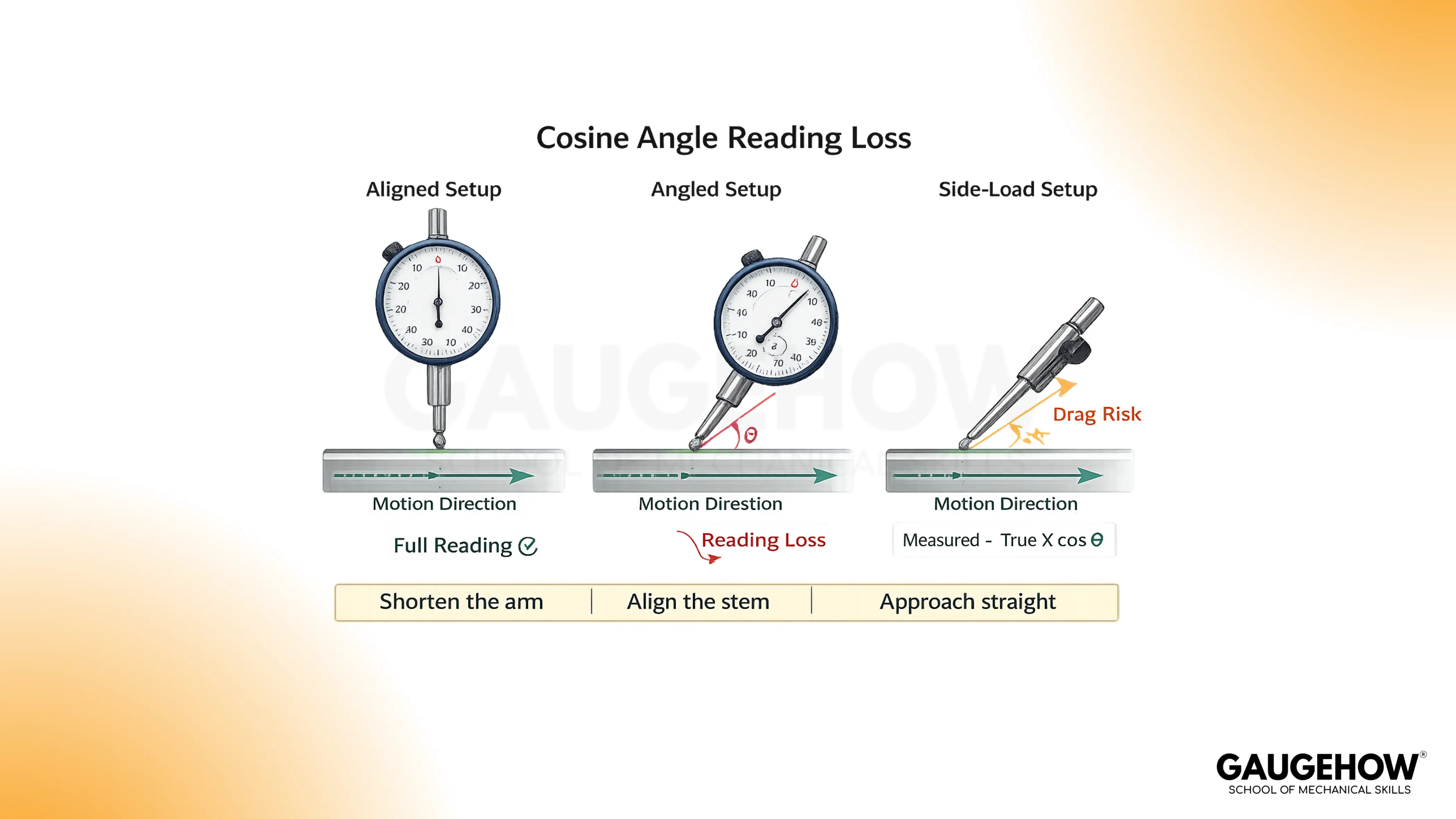
The fix is geometry, not settings. Align the stem closer to the motion line, shorten the arm, and approach straight so the contact does not skid.
Side Load and Stick-Slip
Side load makes the plunger bind, so readings jump rather than track smoothly.
Reduce side load by changing approach direction, improving alignment, and slowing the sweep.
If the contact feels “grabby,” the setup is telling you the reading is not clean.
End of Travel Behavior
Near the end of travel, spring force and internal friction effects can change.
Stay in a mid-stroke window and keep preload consistent, because that usually improves baseline return and reduces drift.
Temperature and Cleanliness
Warm hands on the stand, coolant films, and chips under the contact point all create drift.
Wipe the contact area, let the setup stabilize, and repeat the same sweep path to see whether the variation is real.
Choosing Between Tools: Digital vs Analog Indicator
The digital vs analog indicator is mainly a decision about reading style, logging needs, and shop abuse, not about “modern versus old.”
Digital displays help with fast recording and handoff, while analog needles can be quicker for trend scanning during machine adjustments.
Angle | Digital | Analog | Best Fit |
Reading style | Numeric capture | Needle trend | Trend scanning favors analog |
Recording | Fast and consistent | Manual transcription | Multi-operator favors digital |
Durability | Electronics and battery | Pure mechanics | Harsh abuse favors analog |
Training | Lower interpretation load | Skill-based reading | Mixed teams favor digital |
Tolerance scanning | Requires attention | Instant needle position | Go/no-go work favors analog |
Calibration and Confidence Habits
Calibration confirms instrument behavior against standards, but it cannot rescue a poor setup.
That is why baseline return and stable peak location are your daily confidence habits, and calibration is your periodic tool health habit.
Interval selection should match consequence. If readings drive acceptance decisions or customer documentation, keep calibration disciplined.
If readings drive internal setup and alignment only, then consistent baseline habits plus periodic calibration typically balance risk and effort.
FAQ
1. Can I treat the displayed value as actual part size?
Only if your setup is built as a comparator against a known reference, and you keep the same datum and approach direction. Otherwise, the reading is a deviation. In practice, treat it as a variation unless a master or calibrated reference defines the size.
2. Why does the baseline change after I move the stand?
Moving the stand changes contact angle and side load, and it can also change stiffness at the contact point. So the baseline shifts even when the part does not. Retouch the datum, keep the approach direction consistent, and shorten the arm until baseline return is stable.
3. Which matters more, resolution or technique?
Technique matters more because resolution only shows what the setup feeds it. A fine display can still show repeatable fiction if friction and angle loss exist. Keep posture rigid, stay mid-stroke, and sweep consistently, and then resolution becomes useful rather than distracting.
4. Why do my peaks move between sweeps?
Peak movement usually means your sweep path changed, the tip is skidding, or friction is releasing each pass differently. Slow down, repeat the same traverse line, and keep preload steady. If peak location stabilizes, the variation is real. If it wanders, the setup is drifting.
5. When should I choose analog instead of digital?
Choose analog when you need fast trend scanning at the machine, and the environment is rough. The needle gives you directional information instantly, so you adjust faster. Choose digital when you need clean logging, easier handoff between operators, and fewer reading interpretation mistakes.


