How to use a Micrometer: Outside Micrometer Technique

A micrometer measures outside size by turning a fine screw into controlled movement. Reliable readings come from three controls: clean contact faces, square seating on the measurement line, and consistent measuring force using the ratchet.
You use an outside micrometer when a few microns or a few thou decide whether a part fits, not just whether it looks close. The tool can measure thickness and diameter with high confidence, but only if the faces are clean, the seat is square, and the closing force is controlled.
Most people find how to use a Micrometer frustrating because it still gives a neat number when a chip sits on the face, the tool lands on a chord of a shaft, or the thimble is tightened by feel instead of the ratchet.
This guide fixes that by giving one bench routine you repeat every time: zero check, correct contact line, ratchet close, sleeve first, thimble second, then one re-seat before you record.
Metric and inch examples are included, along with least count and a clean method for correcting zero error, so your readings hold up when tolerances are tight.
Routine Card
Phase | Focus | Outcome You Want |
Prep | Clean, temperature, zero | Tool starts from a known reference |
Seat | True contact line | Shaft readings land on true diameter |
Close | Controlled force | Soft parts do not compress |
Read | Sleeve then thimble | No missed divisions |
Verify | Repeat once | Value holds when you re-seat |
Named decision rule: CSF Rule = Clean, Square, Force.
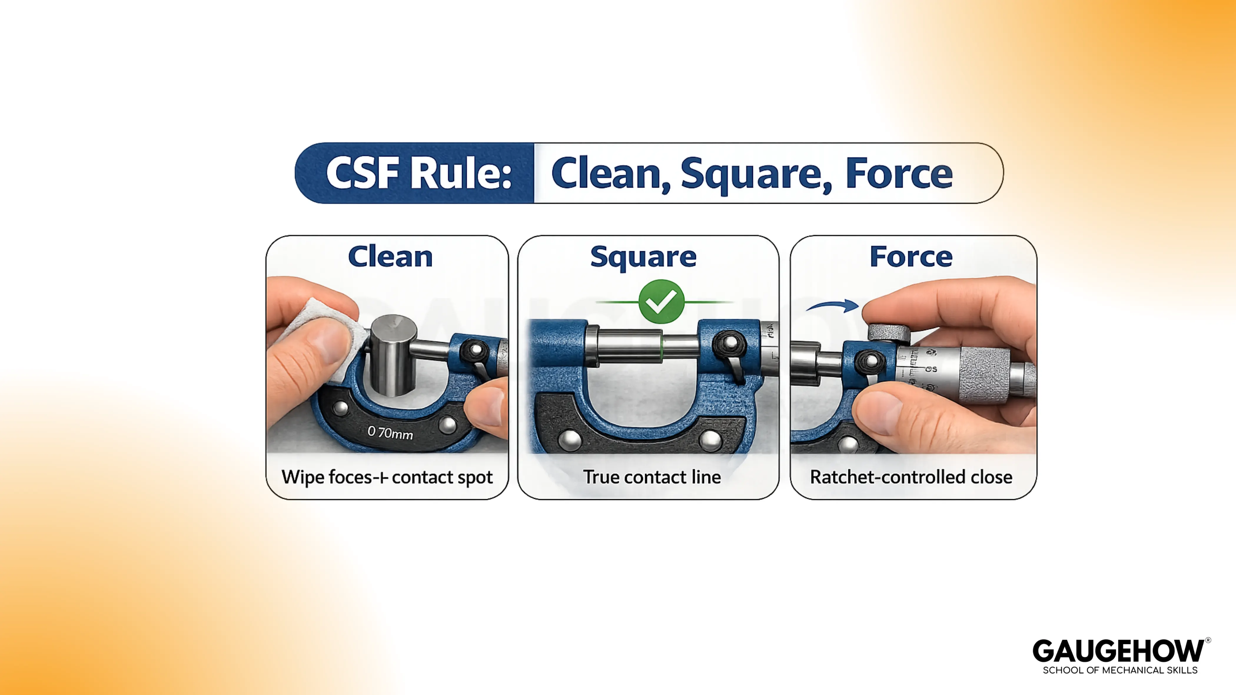
Those three controls decide whether the number deserves trust.
Prep Routine That Stops Drift
Clean faces and the contact line
Wiping the anvil, spindle, and part sounds basic, but it prevents the most common false oversize. Chips, lint, dried coolant, and oil film act like spacers. Burrs can also lift the faces while still letting the thimble “feel smooth,” so the error hides inside a normal-looking closure.
Use light pressure while cleaning. Rubbing hard can drag grit across the face and create scratches that later behave like permanent dirt.
Temperature handling around 20 °C
Room temperature guidance matters because metal expands with heat. Parts straight off machining, grinding, or a warm inspection room can read larger than they will after stabilising. Hands also warm the frame, which shifts the spacing slightly during slow measurements.
Hold the tool lightly and measure after the part settles near 20 °C when the tolerance is tight. Speed helps, too because long handling adds heat.
Zero check habit
Close on clean faces using the ratchet, not finger pressure. Watch the zero alignment. Repeat once. A stable tool returns the same zero point twice. An unstable zero means every reading carries an offset you cannot defend.
Digital outside micrometers still need this step. A display can look confident while the zero reference is wrong.
Outside Micrometer Parts And Tool Choice
Parts that affect accuracy
Frame: Stiffness protects the face spacing from bending under the grip.
Anvil and spindle faces: These are reference surfaces; contamination becomes part of the measurement.
Sleeve and thimble: These define the scale; missing a sleeve mark creates big, believable errors.
Ratchet or friction thimble: This applies consistent force; consistency matters more than strength.
Lock: This holds the spindle position for reading; it helps your eyes, not your seating.
Outside micrometer parts matter because each one either preserves geometry or stabilises force.
Range selection and feel
Choose the correct range instead of forcing travel.
Common metric ranges include 0–25 mm and 25–50 mm; common inch ranges include 0–1 in and 1–2 in.
Staying inside a normal working travel makes the closure feel smoother and reduces the chance of rough thread behaviour affecting force.
Rough travel or “sticky” motion is not a personality issue. Dirt, damage, or lack of lubrication can make the spindle movement inconsistent, which makes force inconsistent, which makes readings inconsistent.
Digital outside micrometer notes
Digital tools reduce reading errors and speed up inspection. Seating, force, heat, burrs, and face contamination still determine accuracy. Zero-set becomes the discipline point, so treat it like a controlled step, not a convenience button.
Outside Micrometer Technique For Flats And Shafts
Flats and soft materials
Flat thickness measurement is stable when both faces land square on the same thickness line. Tilt creates a diagonal reading, so the number changes with small hand movement. Soft materials add another issue: contact force can compress the surface and create a false undersize.
Use the ratchet because it limits force. Avoid “just a little more” pressure. Extra pressure can mark soft parts and move the reading while still feeling controlled.
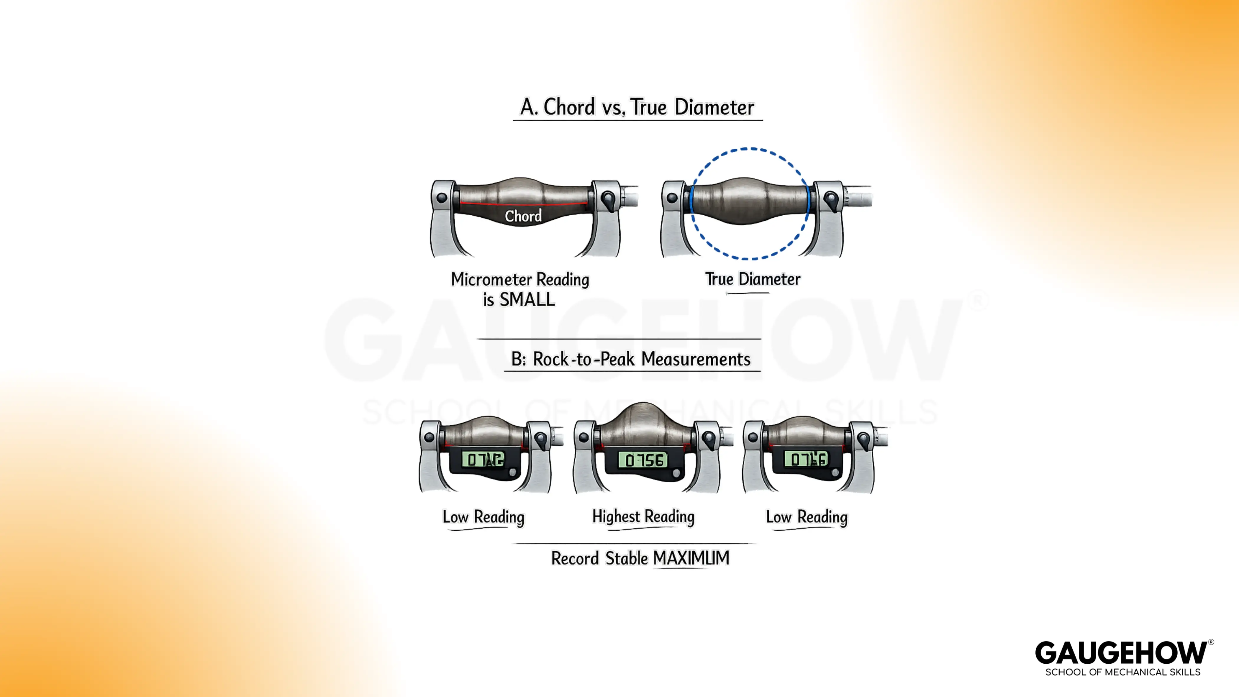
Shafts, cosine error, and peak seating
Round parts can measure wrong even when the tool feels seated. An angled seat measures a chord across the cylinder rather than the true diameter. That chord is shorter, so the micrometer reads low. Cosine error is simply geometry showing up in your hands.
Peak seating fixes it. Close lightly, then rock across the axis until the reading reaches a stable maximum. That maximum is the closest seat to true diameter because it aligns the faces across the widest line.
Force control and frame deflection
Grip and force matter because the frame can flex. Flex changes the spacing between anvil and spindle, so the micrometer “moves” while you think only the spindle is moving. Light handling and ratchet-controlled closing prevent this without adding complexity.
Step-By-Step Outside Micrometer Routine
1. Clean the faces and the part where contact will land
A hidden chip can add an error larger than the tool’s resolution. You are finished when the faces close smoothly and look clean under light.
2. Set the opening slightly larger than the part
Approach without bumping edges. A clean approach protects faces and avoids jolting the seat. You are finished when the part fits between the faces without forcing.
3. Set the tool square on the measurement line
Square seating prevents diagonal readings. On a shaft, light rocking should move the reading up to a clear maximum rather than drifting randomly.
4. Close to contact using the thimble, then finish with the ratchet
Consistent force prevents soft-part compression and frame flex from changing the number. Stop at a controlled closure, typically two or three light clicks, rather than chasing a “tight” feel.
5. Lock only after the seat feels stable
Locking early preserves a bad seat. Locking after a good seat preserves a good seat while you read. You are finished when the value does not shift as your grip relaxes.
6. Read sleeve first, then thimble, then add once
Order prevents missed divisions. You are finished when the sleeve value is written down before you look for the thimble line.
7. Lift, re-seat, and read again before recording
Repeatability is the proof step. You are finished when both readings agree within the tool’s resolution.
How to read a micrometer
Reading works when your order never changes. Under this heading, How to read a micrometer means sleeve first, thimble second, then add once with units.
Read order
The sleeve gives the main value.
Thimble adds the fine increment.
Vernier, if present, refines one more digit.
Write the sleeve value first. That one habit prevents most misreads.
Metric example
Sleeve shows 7.50 mm.
Thimble aligns with 23 divisions.
Result: 7.50 mm + 0.23 mm = 7.73 mm.
Inch example
Sleeve shows 0.275 in.
Thimble aligns with 14 divisions.
Result: 0.275 in + 0.014 in = 0.289 in.
Vernier note
Vernier lines add another decimal place. Use them only after sleeve and thimble are correct. Extra precision does not rescue a bad seat.
Least count
Least count is the smallest increment your tool can show. It equals screw pitch divided by thimble divisions. A common metric micrometer uses 0.5 mm per turn and 50 divisions, giving 0.01 mm per division.
🔧 Trusted by 23,000+ Happy Learners
Industry-Ready Skills for Mechanical Engineers
Upskill with 40+ courses in Design/CAD, Simulation, FEA/CFD, Manufacturing, Robotics & Industry 4.0.
Micrometer Reading Chart For Metric And Inch
This micrometer reading chart exists to keep your result aligned with the tool’s increments. It also helps catch the two classic mistakes: missing the 0.50 mm sleeve mark in metric and missing the 0.025 in sleeve step in inches.
Metric reference
Scale Element | Value Per Mark |
Sleeve main mark | 1.00 mm |
Sleeve half mark | 0.50 mm |
Thimble division | 0.01 mm |
Vernier line (if present) | 0.001 mm |
Inch reference
Scale Element | Value Per Mark |
Sleeve numbered | 0.100 in |
Sleeve line | 0.025 in |
Thimble division | 0.001 in |
Vernier line (if present) | 0.0001 in |
Two cross-check habits keep mistakes rare:
Compare your final digits to the increment table. A reading that cannot exist usually means a missed sleeve step.
Read the sleeve again after the total is written. If the sleeve value changes, a division was skipped.
Micrometer Zero Error Fix, Verification, And Troubleshooting
Zero error correction
Zero error shows up when clean faces close under controlled force and the tool does not read true zero. Dirt is the first suspect, then shock, wear, or temperature shift. Cleaning and repeating the close matters because adjustment done on dirty faces lock an error into the tool.
A clean micrometer zero error fix follows a simple order:
Clean the faces and close with the ratchet.
Repeat once to confirm the offset is consistent.
Adjust only if your micrometer is designed for it and you have the correct wrench.
Verify the tool on a known standard before trusting production measurements.
Stop trying to “work around it” if zero will not repeat. A tool that cannot repeat at zero cannot be trusted on a part.
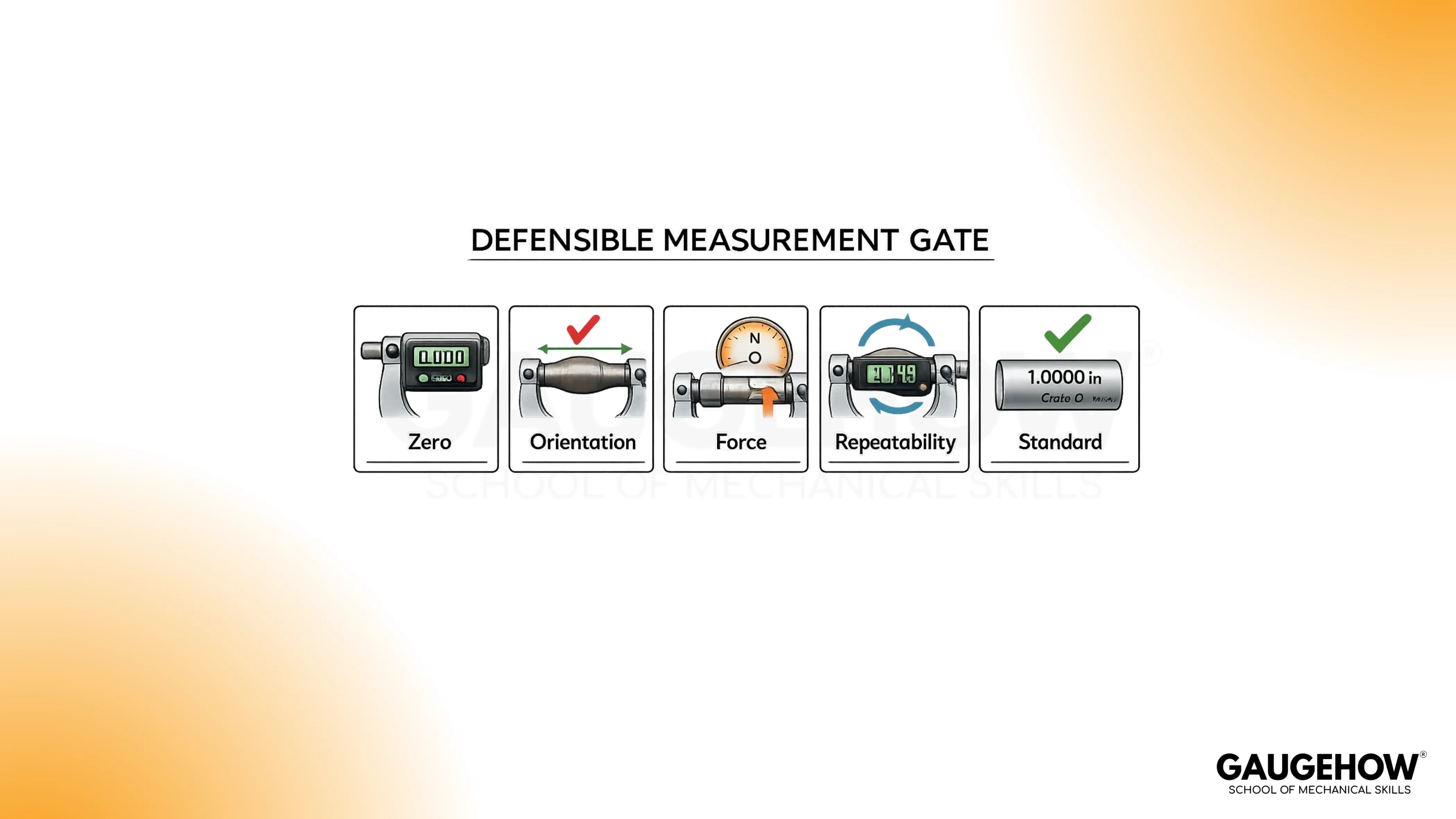
Verification Check
Two proofs matter more than long explanations: repeatability and a standard.
Repeatability comes from taking two readings with a lift and reposition. A stable method returns the same value because the contact geometry and force stayed consistent.
Standard checking means verifying the micrometer against a gauge block, setting standard, or certified pin near the size you care about. This separates tool error from part variation.
A simple way to remember the verification logic is this: once you can prove the tool repeats and matches a standard, how to use a Micrometer becomes a controlled process rather than a skill you “feel” your way into.
Troubleshooting Module
Bench clue | Role | Example action | Expected outcome |
Two readings don’t match | Flags repeatability loss | Lift, re-seat, ratchet-close | Same value twice |
Reading runs high | Flags contamination/burr influence | Wipe faces + contact spot | Value drops, then holds |
Shaft reads small | Flags chord seating | Rock to the maximum | Peak repeats |
Soft part reads small | Flags surface compression | Stop at first ratchet slip | No downward trend |
Zero won’t repeat | Flags unstable reference | Clean, let stabilise | Zero matches twice |
Closure feels rough | Flags tool condition issue | Stop and service tool | Smooth travel returns |
Now the real-world mistakes, explained without fluff:
Warm parts: A hot part reads larger because metal expands. Drift continues until the temperature stabilises. Waiting is faster than chasing changing numbers.
Oil film and chips: Contamination reads as added thickness because it becomes part of the stack between faces. Cleaning fixes the geometry, so the value often drops and becomes stable.
Shaft mis-seating: Angled seating reads a chord rather than diameter, so the value reads low. Peak seating works because the maximum corresponds to the true diameter line.
Excess force: Soft materials compress and frames can flex. Ratchet closing limits force so the number reflects size rather than pressure.
Rough spindle feel: Inconsistent travel creates inconsistent force, so readings wander even with good seating. Service is the right move once roughness appears.
Missed sleeve divisions: A skipped 0.50 mm mark or 0.025 in step produces a wrong number that still looks “reasonable.” Writing the sleeve value first prevents that error.
When calibration is the right decision
Set the tool aside for calibration or repair if any of these show up:
Drop or shock event.
Zero fails to repeat after cleaning and controlled closing.
Standard check does not match within expected accuracy.
Spindle travel remains rough after cleaning.
FAQs
1. Why does the number change when I measure the same part twice?
The tool is landing on a different contact line. A tiny chip, a slight tilt, extra squeeze, or a warmer part shifts the seat, so the screw stops in a different place. On shafts, an angled seat reads a chord, not a diameter.
2. How much pressure is acceptable on soft materials?
Use only the tool’s controlled force. Stop as soon as the ratchet slips. More tightening does not improve accuracy; it compresses the surface, drives the reading smaller, and can leave a mark that changes the next measurement.
3. Why do shaft readings often come out smaller than expected?
The micrometer is not seated across true diameter. A slight angle measures a shorter chord, so the value reads low and varies. Close lightly, then rock across the axis and take the stable maximum as the diameter.
4. Does a digital outside micrometer remove technique errors?
It removes scale-reading mistakes, not measurement mistakes. Dirt, heat, seating angle, and closing force still decide the number. Zero-setting is still required, and consistent force still matters because the display can look stable even when contact is wrong.
5. When does it make sense to switch to a different tool?
Switch when the geometry or requirement doesn’t suit an outside micrometer: internal diameters, deep recesses, thin-walled parts that crush, rough surfaces that won’t seat, or fast go/no-go checks. The right tool reduces seating sensitivity and operator influence.


