How To Use an Inside Micrometer for Internal Diameters

An inside micrometer measures bores and other internal sizes for internal diameter measurement by combining an extension rod setup with a micrometer head reading. Select the correct range, set zero with a master, seat the contacts squarely, rock gently to true size, then record the total.
Covers metric and inch readings, least count, zero setting, and common mistakes that affect bore size decisions.
A bore can sit near the tolerance limit, and one bad touch can change the decision. Inside micrometers are accurate, but only when the rod setup, zero setting, and contact alignment are controlled.
Dirt on a contact, a wrong extension, or a tilted entry can quietly add error. The routine below keeps the measurement repeatable, then the reading section shows the arithmetic in mm and inches.
Inside Micrometer Uses for Internal Diameter Measurement
Inside micrometers are used for larger internal sizes, where caliper internal jaws start losing confidence. They are common in bore checks, housing seats, and machined internal registers.
The tool is especially useful when the surface is accessible,e and a direct reading is preferred over a transfer method.
Use this tool when the bore size matters more than speed, and when the work can be reached without forcing the head or rod at an angle.
Keep a different method ready for small bores, deep interrupted bores, or surfaces that need fast scanning for roundness trends.
Typical Bench Uses
A short list helps here because selection errors begin before the reading starts.
Finished bore size confirmation after machining
Internal seat checks during rework and fitting
Large internal width checks where a rod-type set fits cleanly
Quiet Limits
A bore may look simple, but access path controls reliability. A tight shoulder, burr near the mouth, or interrupted surface can make the contact feel tight before the tool reaches true diameter. In that condition, friction dominates the feel rather than the actual size.
Inside Micrometer Parts and Function
Understanding the parts removes half the reading mistakes because each part changes either the range, the contact condition, or the arithmetic.
Main Parts And Their Roles
Part Name | Role | Quiet Risk | Bench Habit |
Measuring Head | Creates the fine micrometer movement and scale reading | Forced rotation under side load damages the feel | Turn only after the contacts are roughly aligned |
Extension Rod | Sets the measurement range window | The wrong rod creates a wrong total, even with a correct head reading | Match rod to expected size before insertion |
Spacer Collar | Adds a fixed length to bridge ranges | Spacer omitted in math gives a false low result | Record spacer value before taking the final reading |
Contact Tips | Touch the bore walls and define the size | Dirt or burrs mimic a tight bore | Wipe both tips and the bore mouth before entry |
Lock Screw | Holds a settled reading for safe viewing | Locking too early captures a tilted condition | Lock only after rocking and repeat check |
Handle | Improves control and reduces hand heat on longer setups | Gripping the head warms the tool and changes feel | Hold the handle or rod area, not the sleeve |
Part Use Order
Set the rod and spacer first, then confirm the expected range, and then do the zero setting. After that, touch the bore and find the true seating position.
Reading before this sequence usually creates a clean-looking number that is wrong for a very ordinary reason.
How To Use an Inside Micrometer for Internal Diameters
This routine is written for extension rod-type analog sets, but the same control habits apply to similar inside micrometers.
Step By Step Routine
Clean the contacts, rod joints, and bore entry.
Select the rod and spacer for the expected range.
Set zero with the same setup used on the part.
Insert under size, then expand to light contact.
Rock gently to true seating, then lock and read.
Reseat once and confirm the number repeats.
Pre-Measurement Setup
Clean the contact faces, rod joints, and bore entrance. Check that the extension rod seats fully and threads smoothly.
Confirm the expected size range from the drawing or prior process reading, so the selected rod and spacer combination is already in the right window before insertion.
How To Zero an Inside Micrometer Using Setting Master
Use the selected rod and spacer combination during zero setting, because the setup must match the setup used on the part. Bring the contacts into the setting master gently, then confirm the zero alignment.
If the index lines do not agree, lock the spindle and adjust the sleeve with the spanner, then recheck the setting again.
A practical habit matters here. Repeat the zero check after any rod change, after a dropped tool, and after a long pause on a warm bench.
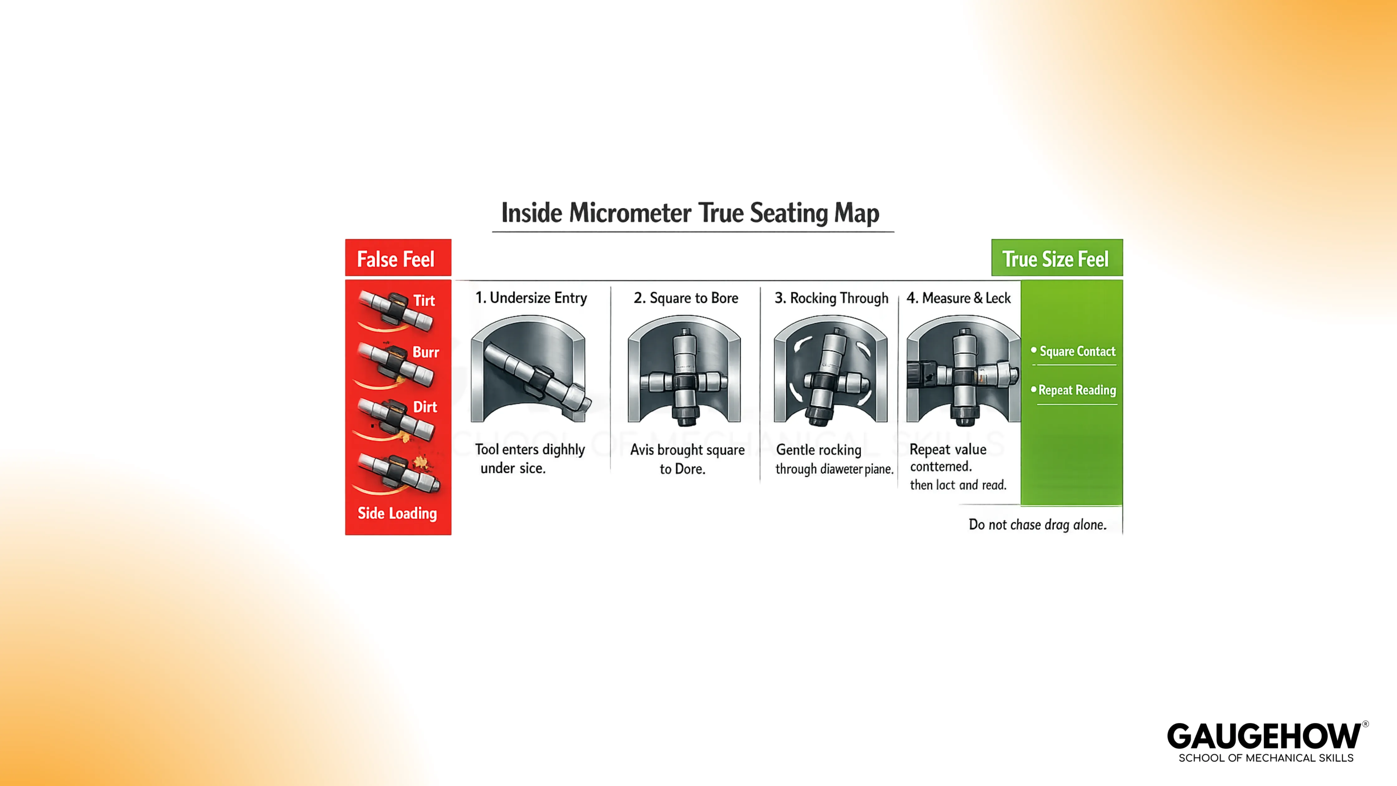
Contact Seating And True Size Feel
Insert the tool slightly under size, then expand until both contacts touch. Keep the axis square to the bore as you bring the contacts into light contact.
Rock the tool gently through the diameter plane, because the true size is found at the point where the contact condition settles and the reading repeats.
Do not chase drag alone. Drag can increase from tilt, dirt, oil film, or a burr, and the tool can feel tight while still sitting off the true diameter.
Multi-Point Check Inside The Same Bore
Take at least two positions at the same depth with a rotated angle between checks.
Add another set at a second depth when taper is possible.
This practice separates local contact feel from actual size behavior of the bore.
Recording Habit That Survives Rechecks
Write the rod value, spacer value, head reading, final size, and measurement location.
Add depth and clock position when the part may be oval or tapered.
A full record prevents arguments later because the second operator can repeat the same condition.
Inside Micrometer Reading Formula And Least Count
Reading becomes simple when the arithmetic is split into fixed-length and micrometer head movement. The fixed length comes from the rod and spacer setup. The head contributes to the fine adjustment of reading.
Working Principle
The thimble rotates a precision screw, and that screw turns rotary motion into linear travel.
Each full turn moves the spindle by one pitch amount.
The scale divides that movement into smaller, readable increments.
Least Count
Least count is the smallest readable increment from the micrometer head. For a common metric head:
Least Count = Screw Pitch ÷ Thimble Divisions
Take a simple example and calculate it step by step.
Pitch = 0.5 mm
Thimble divisions = 50
0.5 ÷ 50 = 0.01 mm
So the least count is 0.01 mm.
This value sets the reading resolution of the head, but the total size still depends on the rod and spacer values added to it.
🔧 Trusted by 23,000+ Happy Learners
Industry-Ready Skills for Mechanical Engineers
Upskill with 40+ courses in Design/CAD, Simulation, FEA/CFD, Manufacturing, Robotics & Industry 4.0.
Formula For Total Size With Rod And Spacer
Write the total in this form every time, and list the parts separately before adding.
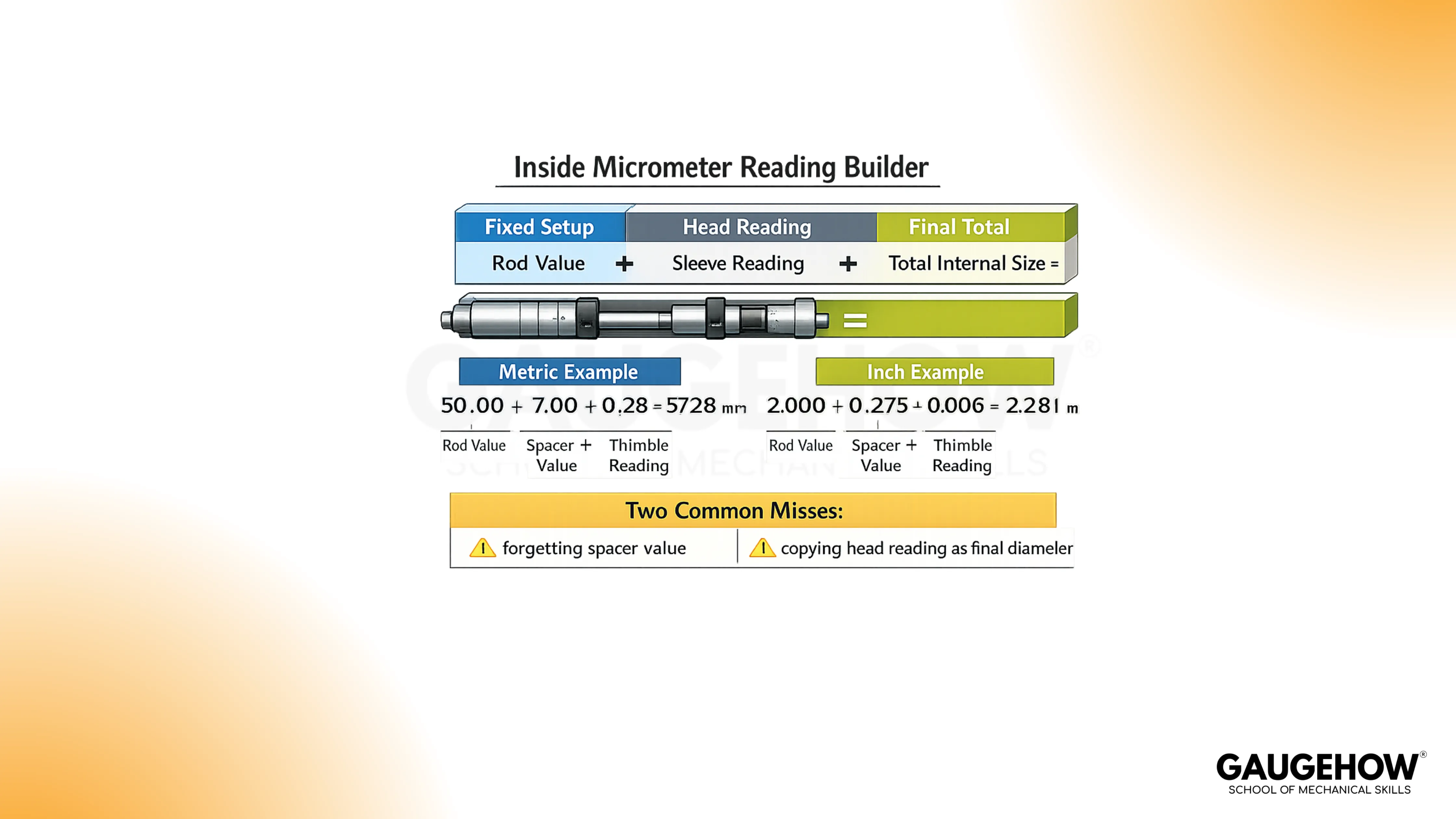
Total Internal Size = Rod Value + Spacer Value + Sleeve Reading + Thimble Reading
That format avoids the two common misses, which are forgetting the spacer and copying the head reading as the final diameter.
Worked Examples In MM And Inches
Examples should read like bench notes. Keep the sequence the same each time, so the arithmetic does not change when the pressure rises during inspection.
How To Read an Inside Micrometer in MM
Start with a 50 mm rod setup and no spacer. After sitting and rocking in the chair, read the head as follows.
Sleeve reading = 7.00 mm
Thimble reading = 0.28 mm
Add the head first.
7.00 + 0.28 = 7.28 mm
Now add the rod value.
50.00 + 7.28 = 57.28 mm
Final bore size = 57.28 mm
The same sequence works even when the head is near a boundary mark. Read the sleeve first, then the thimble, and then add the fixed setup values.
Inch Example With Extension Rod
Start with a 2.000 in rod setup and no spacer. After true seating is confirmed, read the head.
Sleeve reading = 0.275 in
Thimble reading = 0.006 in
Add the head first.
0.275 + 0.006 = 0.281 in
Now add the rod value.
2.000 + 0.281 = 2.281 in
Final bore size = 2.281 in
The inside micrometer reading becomes trustworthy only after repeated seating produces the same value. Take one more check after unlocking and reseating, especially on close-tolerance bores.
Formula Check Before Signing Off
Read the total aloud in parts before writing the final result. Rod, spacer, sleeve, and thimble should each appear in your note. This simple habit catches missing values faster than remeasuring an already removed part.
Errors, Zero Error, And Tool Choice
Most wrong results come from setup conditions, alignment, or contact behavior rather than bad scale reading.
For how to use an Inside Micrometer in production, the control habits below matter more than speed.
Zero Error And Reference Setting Drift
If zero shifts after setup, every result shifts with it. A mis-set sleeve, a rod change without reset, or contact contamination can move the reference condition.
Recheck against the same master when readings begin to drift or after any setup change.
Keep the same phrase as a routine reminder on the bench, how to zero an inside micrometer using the setting master, because that step decides whether the next ten readings mean anything.
Inside Micrometer Alignment Error
An inside micrometer alignment error happens when the tool axis is not square to the bore diameter plane. The contact touch early, the feel seems firm, and the size can be read high.
Rocking through the contact point and checking repeatability exposes this fast.
Write the condition in the record when access is poor, because a difficult approach can affect internal diameter measurement even with a careful operator.
Common Failure Modes And Fast Checks
Trigger | Result | Fast Check | Daily Habit |
Dirt or burr on the contact tip or bore mouth | False high or unstable value | Clean and remeasure before adjusting setup | Wipe tips and bore entry every reading cycle |
Wrong rod or missed spacer in arithmetic | Large offset error with clean repeatability | Rebuild the math from parts in the notebook | Record the rod and spacer before touching the bore |
Tilted entry and side loading | Tight fit with the wrong size | Rock through the diameter and look for a repeat match | Approach under size and square the axis first |
Hand heat on head during long checks | Slow drift across repeated readings | Compare against master after pause | Hold the handle or rod area during measurement |
Locking before true seating | Repeatable wrong capture | Unlock, reseat, and compare a second value | Lock only after rocking and confirmation |
How To Measure Bore Diameter with an Inside Micrometer
Choose the inside micrometer for direct size confirmation when the bore is reachable, and the diameter range suits the rod set.
For geometry mapping across many depths and angles, a dial bore gauge is often faster. The strong habit is to separate size confirmation from form scanning rather than forcing one tool to do both jobs.
Tool Choice For Common Bench Situations
Used For | Best Fit | Advantage | Quiet Risk | Bench Habit |
Direct bore size check | Inside micrometer | Direct numeric reading | Alignment feel depends on operator | Repeat at two angles |
Bore trend across depth | Dial bore gauge | Fast comparative sweep | Needs a good master setting | Zero on master before scan |
Quick shop check | Caliper internal jaws | Fast and accessible | Lower confidence near tight limits | Confirm final size with a micrometer tool |
Transfer from awkward bore | Telescoping gauge plus outside micrometer | Reaches some difficult spots | Skill-sensitive transfer feel | Take multiple transfers and compare |
FAQs
1) Do I Need To Reset Zero After Changing The Extension Rod?
Yes. Rod and spacer changes alter the active setup, so reset against the same master before measuring the part. A quick repeat check after reset prevents a full batch of shifted readings.
2) Why Does The Reading Change When I Rotate The Tool In The Bore?
The contact condition changes with alignment and bore form. Recheck at two angles and two depths. That routine separates seating error from actual ovality or taper, and it improves confidence before release.
3) Is Least Count The Same As Accuracy?
No. Least count is the smallest readable increment of the head scale. Accuracy also depends on setup, zero condition, alignment, contact cleanliness, temperature, and operator technique during measurement.
For trainees asking how to read an inside micrometer in mm, the safer habit is to write rod value, sleeve value, and thimble value on separate lines before adding.
4) Can I Use One Reading To Accept A Bore?
For rough process checks, one reading may guide the next machining step. For final acceptance, repeat the measurement after reseating and add rotated or depth checks when the bore can show taper or ovality.
The routine for how to measure bore diameter with an inside micrometer starts with range selection and zero setting, then it moves to contact seating and repeated checks.
5) Which Skill Matters Most For Repeatable Results?
Controlled seating matters most because the scale can only report the contact condition you create. Practice the same entry angle, rocking motion, and recording sequence until the value repeats before you lock it.


