How to use Vernier Caliper: Step-by-Step, Zero Error

A vernier caliper is a manual precision tool for depth measurements. To learn How to use Vernier Caliper, set the jaws lightly, read the main scale, find the aligned vernier line, add the fraction, then re-seat to confirm.
You use a vernier caliper when you need a dependable size, not a rough estimate. The tool can read external, internal, and depth dimensions, but only if the jaws are seated correctly and your eye angle is controlled.
Most people find a vernier caliper hard because the tool gives a number even when the jaws are not seated square, the scale is read from an angle, or the zero is not true.
This guide fixes that by giving one routine you repeat every time: zero check, correct contact points, main scale first, vernier line second, then one re-seat check before you record the value.
Metric and inch examples are included, along with least count and a clean method for correcting zero error, so you can measure confidently even when tolerances are tight.
Parts of a Vernier Caliper
You get reliable readings faster when you know which surface is actually doing the measuring.
Part | Role | Advantage | Example use |
Main scale | Coarse value in mm or inches | Quick baseline | “Last mark passed” |
Vernier scale | Fine fraction between main marks | Higher resolution | Coincidence line |
Outside jaws | External dimensions | Flat reference faces | Shaft diameter |
Inside jaws | Internal dimensions | Reaches into bores | Hole diameter |
Depth rod | Depth measurements | Recess and hole depth | Counterbore depth |
Lock screw | Holds position for reading | Stops drift | Record a value |
Thumb wheel (if present) | Controlled sliding | Smoother seating | Fine approach to contact |
A small habit that helps: treat the jaw faces like reference surfaces. Keep them clean, keep them square, and never force them shut on a burr.
Vernier Caliper Calibration
A caliper can look fine and still read wrong if the jaws are dirty, the slider has play, or the zero is offset. A quick vernier caliper calibration check before you measure saves you from recording a number you later cannot explain.
Wipe the measuring faces. Use a clean cloth or paper. Dirt is a hidden spacer.
Close the jaws with light pressure. Do not squeeze. You are checking alignment, not clamping force.
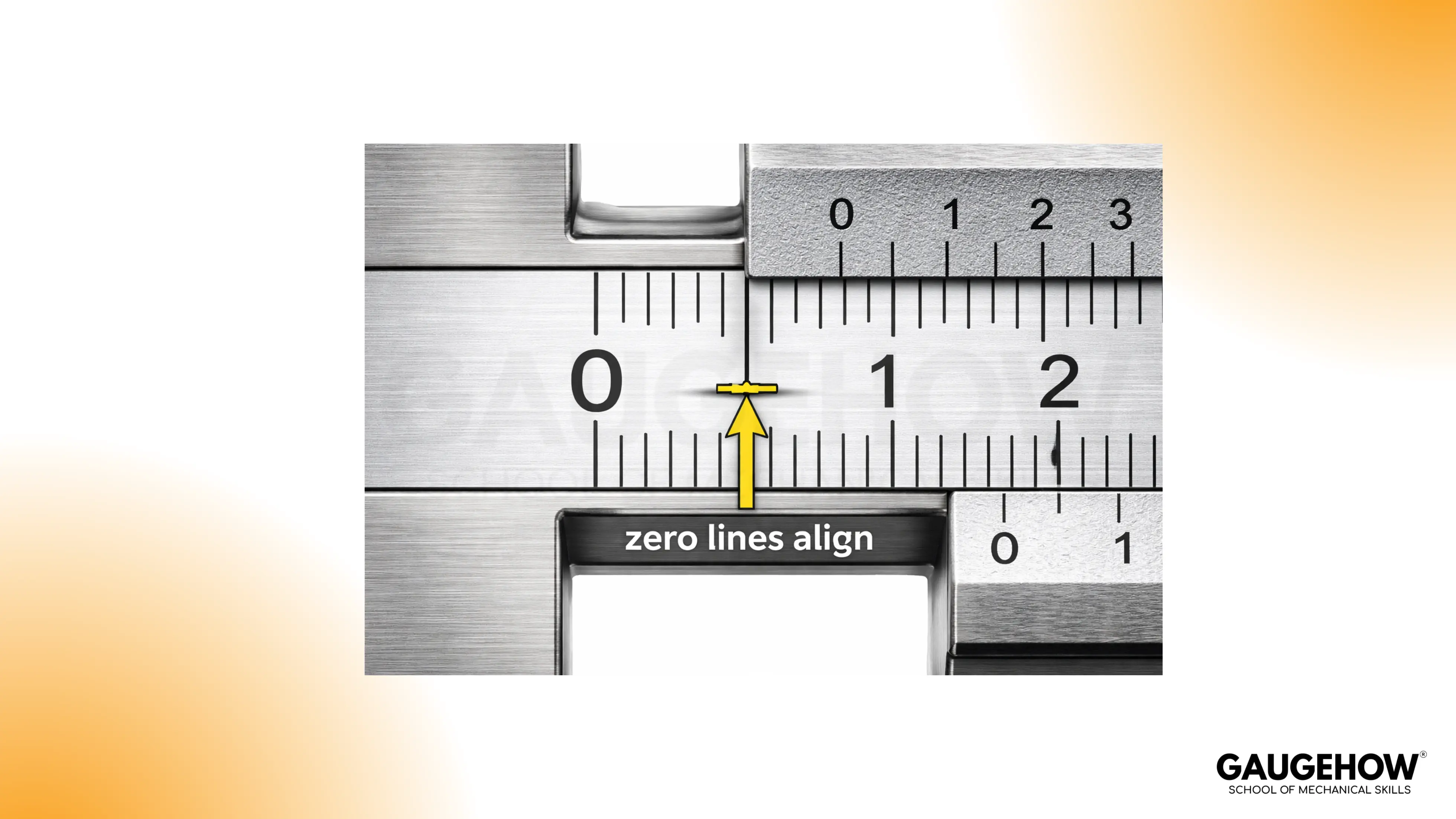
Confirm zero alignment. The main zero and vernier zero should line up.
Slide open and close again. Repeat the zero check. A good tool gives the same result twice.
Lock, then read. If the reading changes when you lock, the lock screw is influencing the slider.
If zero does not align, you can still measure, but you must correct for zero error every time. That is covered later.
How to read vernier caliper
The fastest way to stop second-guessing is to follow the same six steps every time. The point of how to read vernier caliper is not memorising theory. It is building a repeatable bench routine that survives fatigue, shop noise, and tight tolerances.
Reading steps
Clean the part and the caliper faces. One speck of grit can shift a tight tolerance call.
Choose the right contact points. Outside jaws for OD, inside jaws for ID, depth rod for depth.
Seat with light pressure. Close until contact, then confirm there is no rocking.
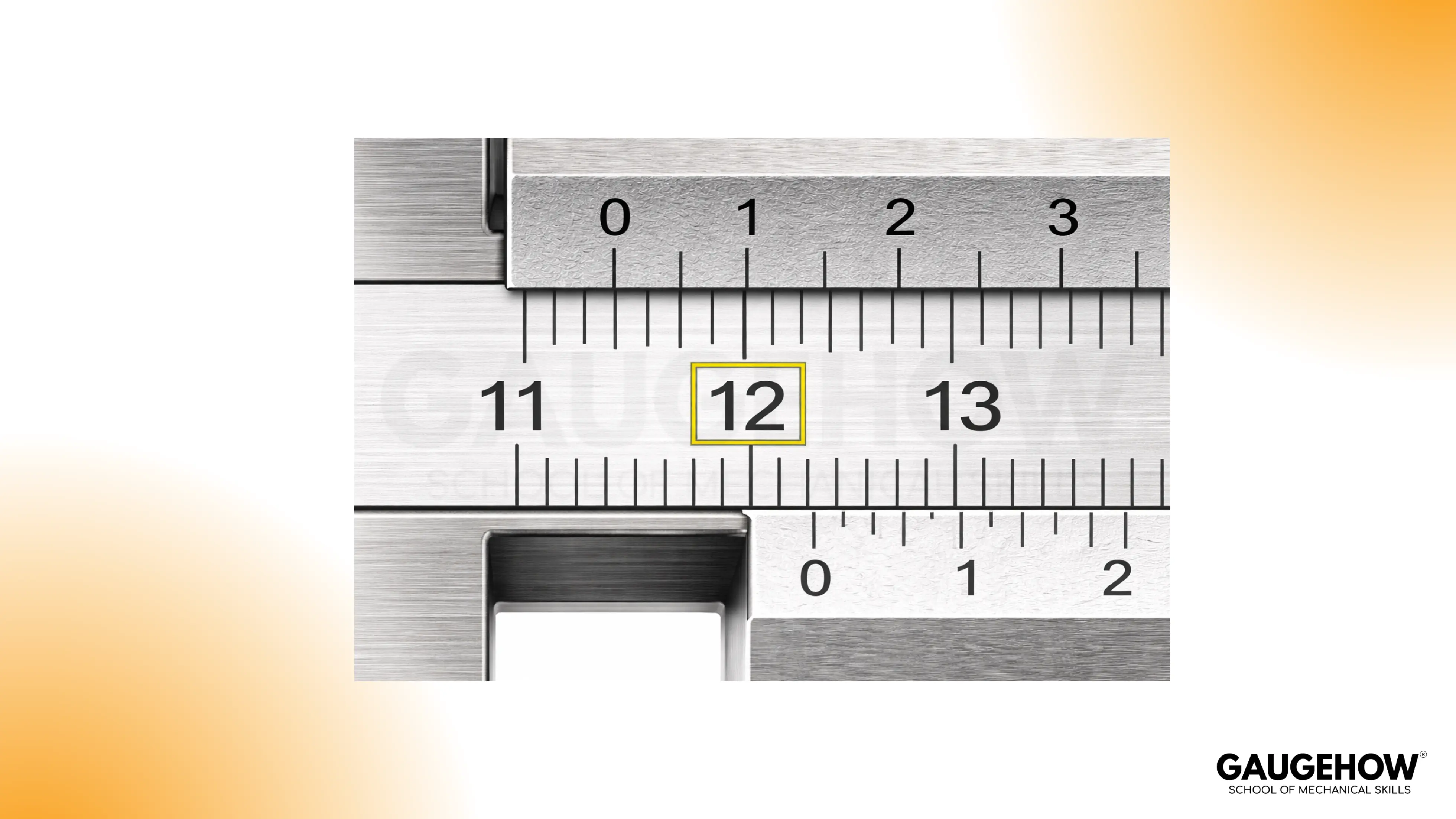
Read the main scale first. Note the last full mark passed by the vernier zero.
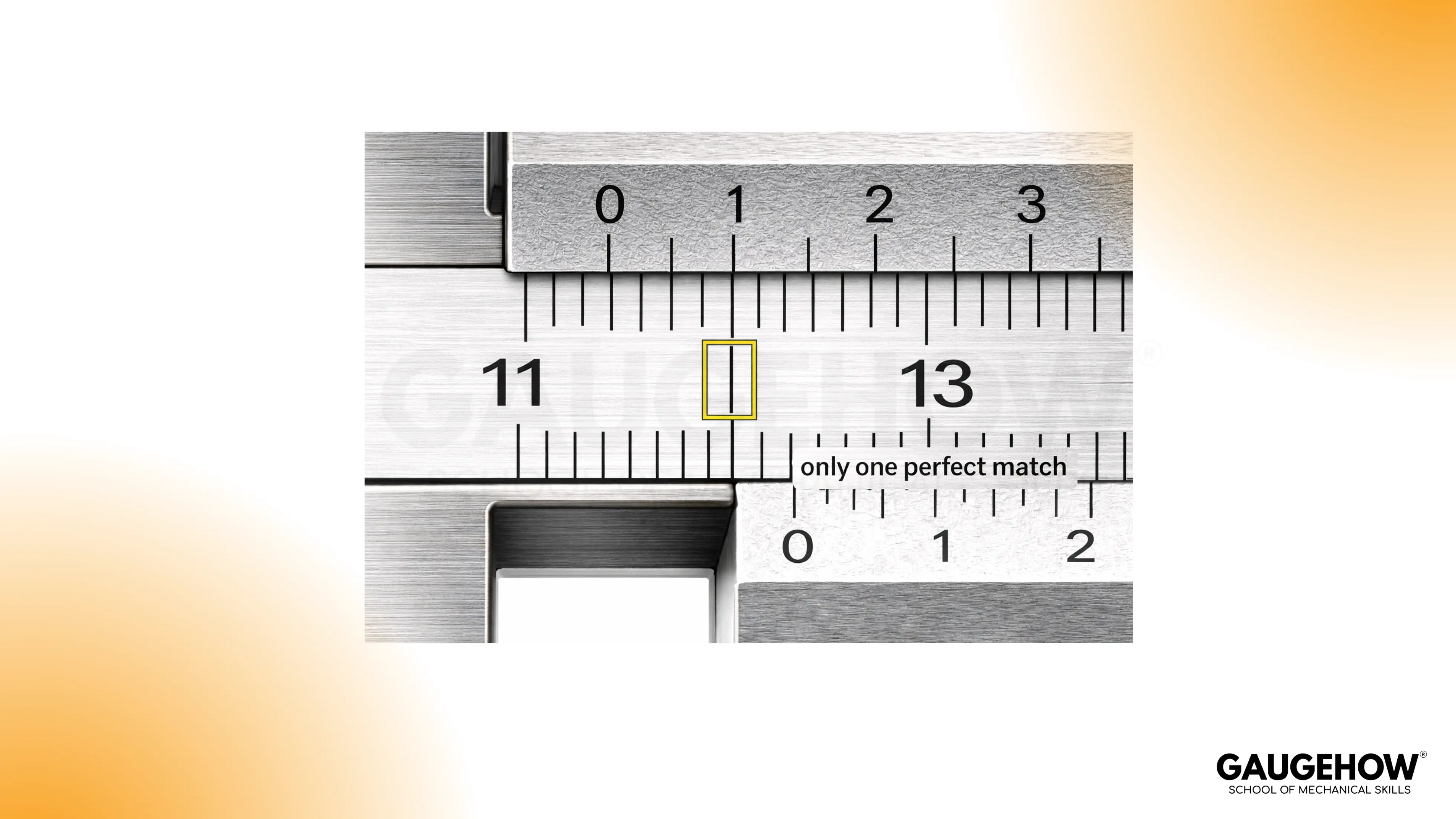
Find the coincidence line. Identify the single vernier line that perfectly aligns with a main scale line.
Add and confirm. Add the vernier fraction to the main scale reading, then re-seat and confirm you get the same value.
A simple reliability habit: if a value matters, do not record the first reading. Re-seat once and confirm repeatability.
The Formula for Reading the Vernier Caliper
The arithmetic is short. The discipline is in picking the right vernier line and staying consistent with units.
Total measurement = main scale reading + (coincidence number × least count)
The main scale reading is the last full mark before the vernier zero.
The coincidence number is the vernier division that lines up exactly with a main scale line.
The least count is the resolution of your specific caliper, based on its scale.
Treat the formula like a check, not a replacement for the physical routine. If your seating is wrong, clean math still gives a wrong number.
What Is Least Count?
Least count is the smallest increment your caliper can resolve. It is the value of one step on the vernier scale.
Most calipers have the least count printed on the vernier. If it is not printed, you can calculate it.
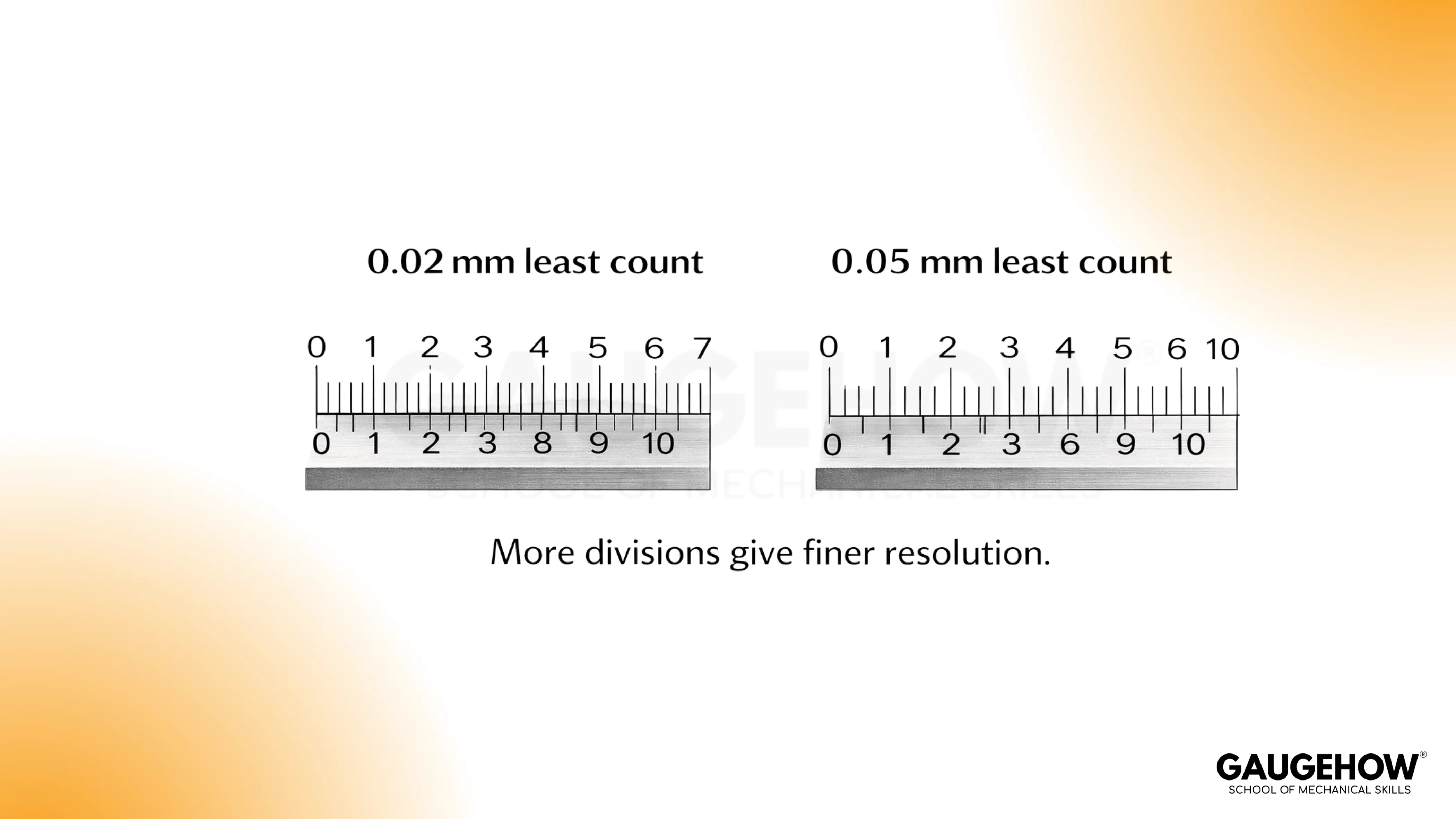
Least Count = value of one main-scale division ÷ number of vernier divisions
Metric example (common workshop caliper)
Main scale division: 1 mm
Vernier divisions: 50
Least count: 1 ÷ 50 = 0.02 mm
That means each step on the vernier represents 0.02 mm.
Inch example (common vernier in imperial)
Main scale division: 0.025 in
Vernier divisions: 25
Least count: 0.025 ÷ 25 = 0.001 in
That means each step on the vernier represents 0.001 in, which is one thousandth.
Two practical notes
Least count is not accuracy. It is a resolution. Dirt, seating, and jaw wear determine accuracy.
Least count must suit the tolerance. If the tolerance band is near your resolution, switch tools or change method.
A quick sanity check helps: re-seat and confirm the same coincidence line twice. Repeatability is your real quality gate.
🔧 Trusted by 23,000+ Happy Learners
Industry-Ready Skills for Mechanical Engineers
Upskill with 40+ courses in Design/CAD, Simulation, FEA/CFD, Manufacturing, Robotics & Industry 4.0.
How to Read a Caliper in Inches
Inch vernier scales look harder because the main scale is often in fractional increments, but the method stays identical.
Example (inches):
Main scale reading: The vernier zero has passed 0.500 in, but not 0.525 in, so main scale = 0.500 in
Coincidence number: The 9th vernier line aligns perfectly
Least count: 0.001 in
Vernier fraction: 9 × 0.001 = 0.009 in
Final reading: 0.500 + 0.009 = 0.509 in
In inches, unit discipline matters. Keep everything in inches until the end. Convert only after you have a final value.
Common Mistakes When Reading Calipers: Zero Error, Parallax Error, and Misalignment
Most wrong readings come from a small technique detail, not the vernier math. If something feels off, slow down for one reset, then read again.
Zero Error
A caliper should read zero with the jaws gently closed. If it does not, every measurement carries that offset.
Close the jaws lightly, then look at the zero alignment.
Open a little, close again, and confirm the same offset shows up.
Clean the faces before you correct anything, dirt can imitate a zero shift.
Apply the correction consistently:
A positive reading at closed jaws means you subtract that amount from your measurement
A negative reading at closed jaws means you add that amount to your measurement
For close-tolerance work, confirm zero again after the measurement. It tells you the tool stayed stable.
Parallax Error
Parallax is simply reading the scale from an angle. The lines look aligned until you change your viewpoint.
Bring your eye directly above the scale, then choose the one vernier line that truly lines up.
If two lines seem almost aligned, your viewing angle is usually the reason.
A small head movement is a good reality check. True alignment stays aligned.
A calm habit to avoid parallax error vernier is to pause for a second, square your viewpoint, then read once without chasing the lines.
Misalignment and Uneven Pressure
A caliper measures best with light, even contact. Heavy pressure and a tilted seat create readings that drift.
Seat the jaws, then feel for a steady contact, not a squeeze.
If the reading changes as you gently rock the tool, the jaws are not seated square.
Re-seat with lighter pressure, then keep the beam aligned with the surface you are measuring.
Lock the slider only after the seat feels stable, and do not overtighten the lock.
Dirt, Burrs, and Oil Film
A tiny burr or chip can add more error than your least count.
Wipe the jaw faces and the part, then measure again.
If the number jumps after cleaning, the first reading was measuring contamination.
Deburr edges that touch the jaws, especially after machining or filing.
Inside Jaws on Chamfers and Radii
Inside measurements go wrong when the jaw tips sit on a chamfer or radius instead of the true bore.
Seat the inside jaws deeper into the bore where the surface is truly cylindrical.
Keep the tool square, then re-seat once to confirm repeatability.
If the reading changes with small changes in position, the jaw tips are not on the functional surface.
Depth Rod Not Seated Flat
Depth readings vary when the caliper body is not planted flat on the reference surface.
Set the beam flat first, then extend the depth rod straight down.
Re-seat the base and repeat the reading once. A stable setup gives a stable number.
Watch for rounded edges and fillets, they can fool the rod contact point.
FAQs
1. Why does the number change when I lock the caliper?
Locking can push the slider slightly if you tighten the screw hard. Seat the jaws first, hold that seat, then apply only enough lock to stop movement. If the reading still shifts, re-seat and read without locking, or service the tool if the slider has play.
2. How much pressure should you use on the jaws?
Use light, steady contact. A caliper is not meant to clamp. Too much force can tilt the jaws, flex thin parts, or make the slider creep. If you feel yourself squeezing, back off and re-seat until the contact feels stable and repeatable.
3. Why do I get two different readings on the same part?
Most drift comes from seating and contact points. Burrs, oil film, and small jaw tilt change the contact geometry. Clean both surfaces, re-seat once, and confirm the same value returns. If it does not, rotate the part slightly and check that the jaws are contacting true measurement faces, not an edge radius or chamfer.
4. How do you measure a hole without getting a wrong inside reading?
Inside jaws can sit on a chamfer or a rounded entry, especially on shallow holes. Seat deeper where the bore is truly cylindrical, keep the caliper square, then re-seat once to confirm the reading holds. If the value changes with small shifts, the jaw tips are not on the functional surface yet.
5. What is the quickest way to handle zero error accurately?
Check the closed-jaw reading gently, then repeat once. If the offset is stable, apply the same correction to every measurement until you can resolve the cause. Clean the faces first, because dirt can look like a zero offset. Confirm zero again after a critical reading so you know the offset did not drift mid-measurement.


