Micrometer Screw Gauge: Definition & Outside Parts Guide

A micrometer screw gauge is a precision instrument used to measure small outside dimensions. It measures the outside diameter and thickness between a fixed anvil and a moving spindle.
The screw converts rotation into a controlled linear movement, so readings are fine and repeatable. It is used in physics labs, machine shops, and inspection work for wires, sheets, and small shafts.
Quick Check Item | What It Means | Typical Value Or Outcome | Proof Check Before You Trust It |
What it measures | Outside diameter and thickness | Outside sizes only | Faces sit square on the surface |
Main scales | Sleeve scale and thimble scale | Sleeve gives whole units | Sleeve line is read at eye level |
Fine step | Least count | Often 0.01 mm on metric tools | Least count is confirmed on the tool |
Force control | Ratchet or friction stop | Limits measuring force | Ratchet clicks before you stop |
A correct micrometer result depends on consistent handling. The calculation is simple, but the contact force and approach direction must stay the same.
Most wrong readings come from variable force, backlash from reversing direction, or an angled view of the reference line.
The steps below set one fixed sequence, so the sleeve and thimble values transfer to the final reading without drift.
Key Terms And Scale Logic
1. Sleeve reading means the value on the main scale. It is the whole millimetres, and half millimetres if shown.
2. Thimble divisions mean the circular scale marks. They represent a fraction of one full turn.
3. Pitch means spindle movement in one full rotation.
4. Least count means the smallest step shown by one thimble division.
How The Total Reading Formula Works
The total reading formula combines the sleeve reading, the thimble reading, and the correction for any zero offset.
Total reading (metric) = Sleeve reading + (Thimble divisions × Least count) ± correction
Read sleeve first. Read thimble second. Apply correction last.
Micrometre Screw Gauge Diagram & Parts
The Micrometre Screw Gauge Diagram is labelled below with parts:
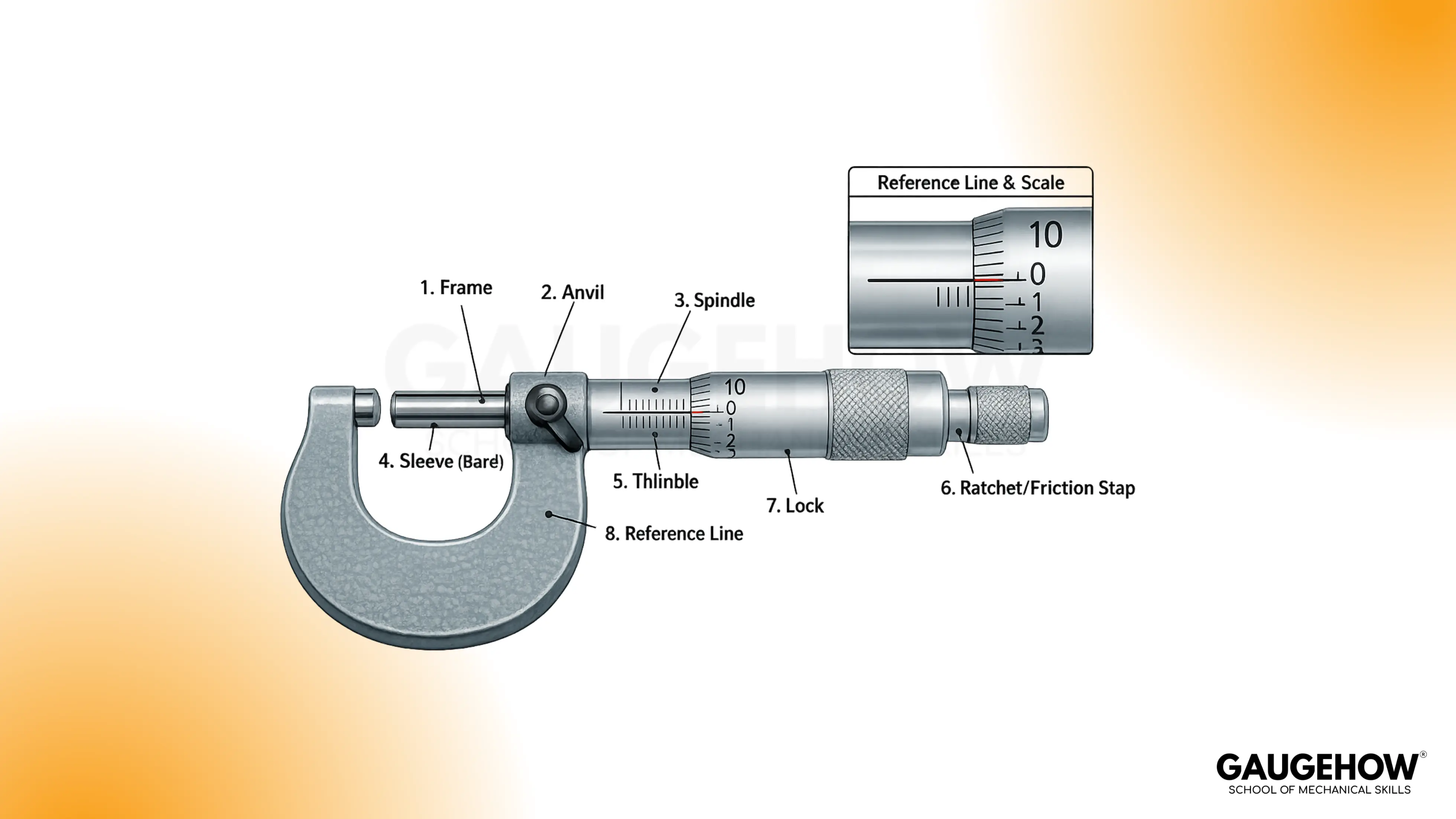
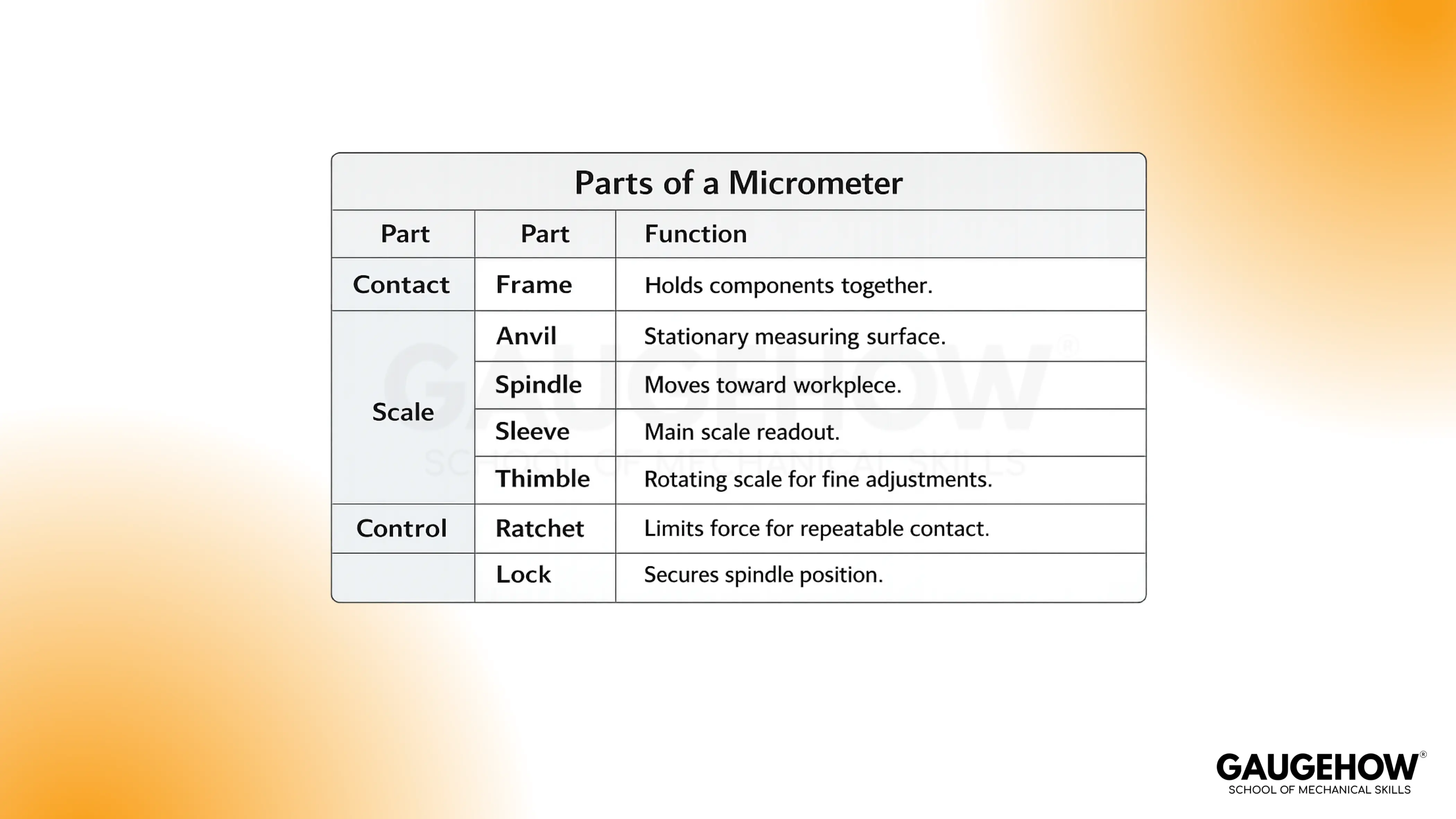
Parts of Micrometre
“In this instrument, the parts of the micrometer consist of contact faces, scales, and a force-control mechanism.”
A stable number needs clean faces. A stable number also needs square seating.
Working Principle
Rotation of the thimble drives the screw, so the spindle advances by a fixed amount per turn. The sleeve gives the main value in whole units, while the thimble supplies the fractional part that lines up with the reference line.
Add the sleeve reading to the thimble contribution to obtain the measurement.
Because the motion is screw-controlled and the force is limited by the ratchet, a small rotation produces a small, repeatable linear movement.
How To Calculate Micrometer Least Count
A micrometer least count is the distance the spindle moves for one thimble division. It comes from splitting one full turn movement into equal divisions.
Least count = Pitch ÷ Number of thimble divisions
Pitch is the spindle travel in one full turn. Thimble divisions are the equal marks around the thimble.
Worked Example (Least Count):
Pitch = 0.5 mm per turn.
Thimble divisions = 50.
Least count = 0.5 ÷ 50 = 0.01 mm.
Use this least count for every thimble conversion on that tool.
Inch Micrometer Basics
An inch micrometer reads in inches using a sleeve scale and a thimble scale. A common model has a measuring range of 0–1 inch. A typical resolution is 0.001 inch. Some types include a vernier to read 0.0001 inch.
Typical inch scale logic is based on 0.025 inch per sleeve division and 25 thimble divisions per turn. This makes one thimble division equal to 0.001 inch.
Tiny inch reading example:
Sleeve reading = 0.275 inch.
Thimble division aligned with the reference line = 12.
Thimble contribution = 12 × 0.001 = 0.012 inch.
Final reading = 0.275 + 0.012 = 0.287 inch.
🔧 Trusted by 23,000+ Happy Learners
Industry-Ready Skills for Mechanical Engineers
Upskill with 40+ courses in Design/CAD, Simulation, FEA/CFD, Manufacturing, Robotics & Industry 4.0.
Types of Micrometers
“In workshop practice, types of micrometers include outside micrometers, inside micrometers, and depth micrometers.”
An outside micrometer measures between two external faces.
An inside micrometer measures internal diameter using internal contacts.
A depth micrometer measures depth from a reference base to a surface.
Reading Methods
Gate item | Pass condition | If it fails |
Zero check | Close gently using the ratchet. Reading must be 0.00 mm, or you record the zero offset and its sign. | Do not measure until the offset is recorded. |
Repeatability check | Measure the same wire at 3 positions along its length. The three readings must be consistent to within one least count. Then take the average. | Re-seat the wire, clean faces, and repeat with the same approach direction. |
A repeatable reading comes from one fixed sequence. Use the Seat–Read–Correct rule. Seat the faces with controlled force. Read the sleeve first, then the thimble. Apply any corrections at the end.
Two-Minute Pre-Check Before Measuring
Close the anvil and spindle using the ratchet. The reading must be 0.00 mm, or you record the zero offset and its sign.
Turn the thimble through a short range. Movement must be smooth and free of sudden jumps.
Check the ratchet operation. It must slip or click before extra force is applied.
Wipe the anvil and spindle faces. Wipe the job surface at the contact points.
Keep one approach direction for all measurements. Do not reverse direction for the final contact.
Step Sequence To Take A Reading
Place the job between the anvil and spindle. Keep the job axis square to the faces.
Turn the thimble until the faces just touch the job.
Use the ratchet for final contact. Stop when the ratchet slips or clicks.
Lock the spindle if the tool has a lock and the reading may shift during handling.
Read the sleeve at the reference line. Record the last visible whole millimetre mark. Add 0.5 mm if the half-millimetre mark is visible.
Read the thimble division that aligns with the reference line. Multiply this division count by the least count.
Add sleeve reading and thimble contribution to obtain the measured reading. Apply zero correction only after this total is formed.
Reading example without error:
Sleeve reading = 12.00 mm.
Half-millimetre line is not visible, so add 0.00 mm.
Thimble division aligned with the reference line = 36.
Least count = 0.01 mm.
Thimble contribution = 36 × 0.01 = 0.36 mm.
Final reading = 12.00 + 0.36 = 12.36 mm.
This result only holds if contact force and seating stay consistent.
Errors And Correction Rules
Error means the micrometer reading differs from the true value by a fixed offset or by a handling effect.
Instrument errors come from the screw and scale zero.
Handling errors comes from force, seating, and approach direction.
The correction must use the correct sign, or the corrected reading moves farther from the true value.
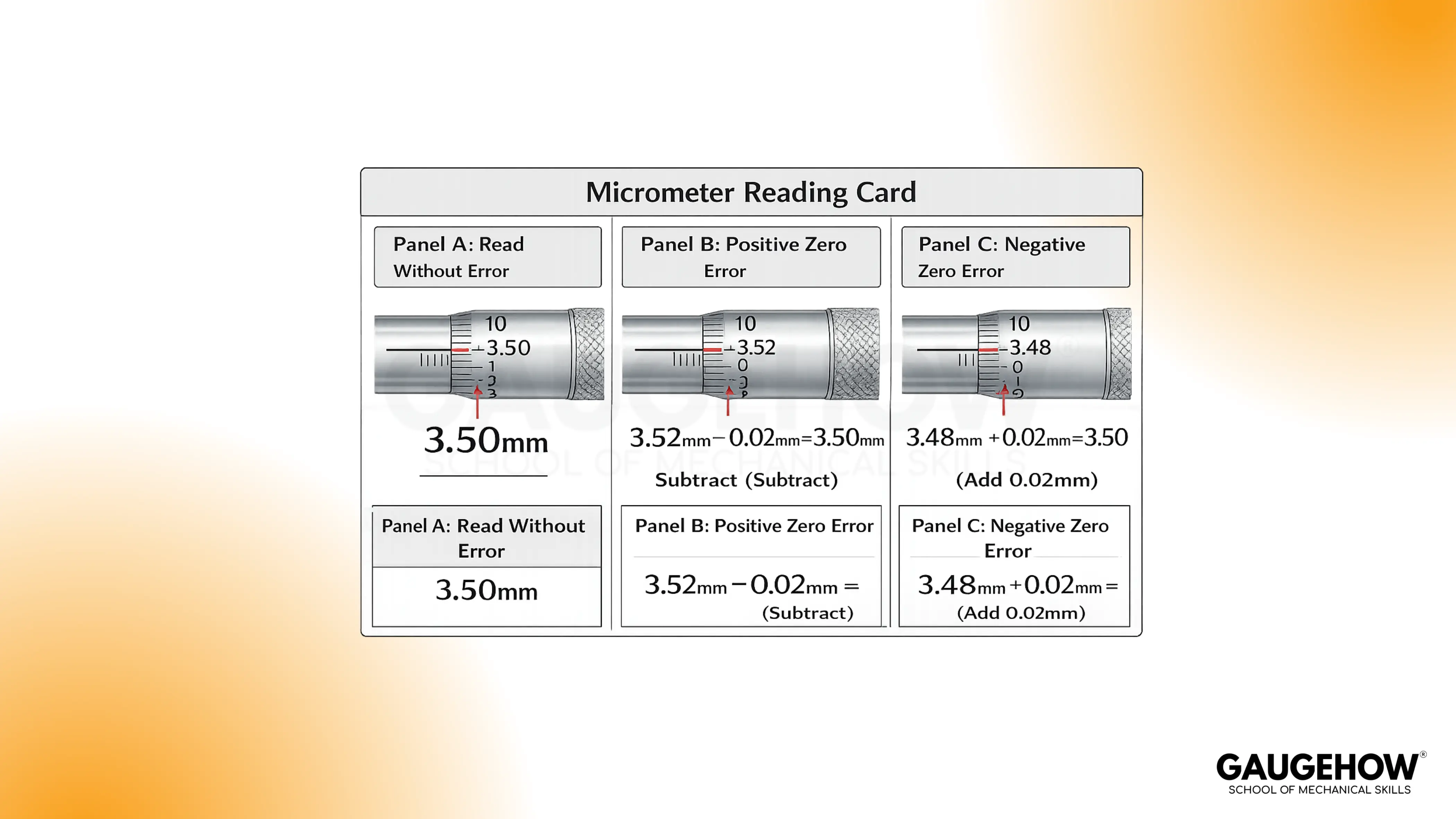
Zero Error
Zero error exists when the faces are fully closed, but the scales do not read zero.
A positive zero error means the instrument reads high at closure.
A negative zero error means it reads low at closure.
The correction must be applied after the measured reading is formed.
Backlash error
It appears when the approach direction changes.
It comes from play in the screw and nut.
Always approach final contact from the same turning direction.
Parallax error
It appears when the eye is not square to the sleeve reference line.
Read at eye level and straight on.
How To Apply Zero Correction
Zero correction is the adjustment applied to the measured reading to remove the zero offset.
Rule:
If the micrometer shows a positive zero error, subtract the error from the measured reading.
If the micrometer shows a negative zero error, add the magnitude to the measured reading.
Worked Example (positive zero error):
Measured reading = 7.73 mm.
Zero error at closure = +0.02 mm.
Corrected reading = 7.73 − 0.02 = 7.71 mm.
A positive error is subtracted because it inflates the measured value.
Worked example (negative zero error):
Measured reading = 12.36 mm.
Zero error at closure = −0.03 mm.
Correction rule: add the magnitude when the zero error is negative.
Corrected reading = 12.36 + 0.03 = 12.39 mm.
Uses of Micrometer
“In measurement work, the uses of micrometer include outside diameter and thickness checks where the faces seat square.” Typical uses include wire diameter, sheet thickness, and small shaft outside diameter. It is also used in inspection because repeatability is high when the ratchet is used.
Limitations come from seating and material behaviour. Soft materials can compress under contact force, so the reading can be low. Burrs, dirt, or a tilted job can hold the faces apart or shift the contact point, so the reading becomes unreliable.
Warm parts can expand during handling, so readings can drift. Inside diameter and depth require an inside micrometer, depth micrometer, or a caliper, because an outside micrometer measures only between two outside faces.
Micrometer vs Vernier caliper
For selection, the micrometer vs vernier caliper comparison below shows what changes the result.
Feature | Outside Micrometer | Vernier Caliper |
Best use | Outside diameter and thickness | Outside, inside, and depth |
Contact force control | Ratchet gives repeatable force | Hand force varies more |
Typical resolution | Often 0.01 mm (metric) | Often 0.02 mm or 0.01 mm, model dependent |
Where it fails | Awkward seating, soft compression | Deep recesses, fine force control |
Pick the tool based on surface seating first. Range comes second.
FAQs
What does the micrometer measure?
It is used for measuring small outside dimensions like thickness and outside diameter. It is preferred when repeatability matters. Flat face contact supports stable readings.
What Is Least Count In A Micrometer?
Least count is the smallest step the tool can show. It is computed from pitch and thimble divisions. LC = pitch ÷ divisions.
How Do I Find Pitch On My Tool?
Pitch is spindle travel in one full turn. Tool markings may state it. A direct check uses one full rotation and observes sleeve movement.
How Do I Apply Zero Error Correction?
A positive zero error is subtracted from the observed reading. A negative zero error is added because subtracting a negative number increases the value. Sign consistency prevents wrong results.
Why Do My Readings Change On The Same Part?
Force, tilt, dirt, and parallax are common causes. Ratchet seating reduces force variation. Repeating a reading after a small reposition checks stability.


