Optical Comparator (Profile Projector): Uses & Advantages

Last updated: Feb 2026
By: QA and Metrology Lead
An Optical Comparator is a non-contact inspection tool that projects a magnified image of a part’s edge onto a screen or camera so you can compare the outline to a scale, overlay, or CAD. It shines for fast 2D profile decisions when alignment, lighting, and verification are controlled.
Best Used For | Mechanism Advantage | Set Up Angle That Matters | False-Call Risk | Better Tool When |
2D outlines, radii, angles, thread forms | Edge geometry is visible and comparable | Datum alignment first, then focus | Fuzzy edges look like size errors | You need a true 3D form or internal geometry |
Quickly compare to a master | Fast pass or fail with overlays | Stable fixturing, repeatable lighting | Overlay misalignment looks like profile error | You need automated reporting and high throughput |
Delicate, flexible, tiny parts | Non-contact reduces part deflection | Contour illumination with clean edges | Part tilt creates “wrong” geometry | Feature is not optically accessible |
Profiles are where good inspection habits matter most. If your result is driven by an edge image, you need a clear datum plan, a repeatable lighting choice, and a short verification routine before trusting numbers.
Do those three well, and this tool becomes a reliable production workhorse rather than a debate generator.
What Is a Profile Projector
A profile projector forms a magnified view of a part and lets you confirm geometry by comparing the visible edge to a reference. That reference can be a screen scale, a reticle, an overlay chart, or a CAD outline. The practical value is speed and clarity on edge-defined features, not just magnification.
It is strongest when the drawing intent is essentially 2D in a controlled view. It is weaker when the requirement depends on hidden geometry, true 3D surfaces, or features that cannot present a stable edge.
An optical comparator works on the principle of
At its core, the optical comparator works on the principle of projecting a magnified image so the visible edge can be aligned to a datum and compared against a reference. Illumination creates contrast, optics magnify, and the stage position and angle reference provide the measurement frame.
Optical Path In Six Steps
Fixture the part so it cannot rock or drift.
Choose illumination mode for the feature, silhouette for outline, reflected for surface detail.
Focus until the edge is stable, not just sharp-looking.
Align to a datum feature, then lock orientation.
Measure or compare using a scale, overlay, or CAD.
Record results using one interpretation rule and one approach direction.
Form Check Discipline
A good form check starts with one question: which edge defines function? Choose a datum that reflects how the part locates in the assembly, then align to that datum before chasing numbers.
Use contour illumination when the outline defines the requirement, and use reflected illumination only when the surface feature is the requirement.
A false edge usually looks like a gray band, a double boundary, or a “breathing” edge that changes with tiny focus shifts. When you see that, fix lighting, cleanliness, and focus before you trust any dimension.
Edge Quality Controls
If you want repeatable outcomes, treat these as controls, not preferences: illumination mode, light intensity stability, part cleanliness, focus discipline, stage approach direction, and a single edge interpretation rule.
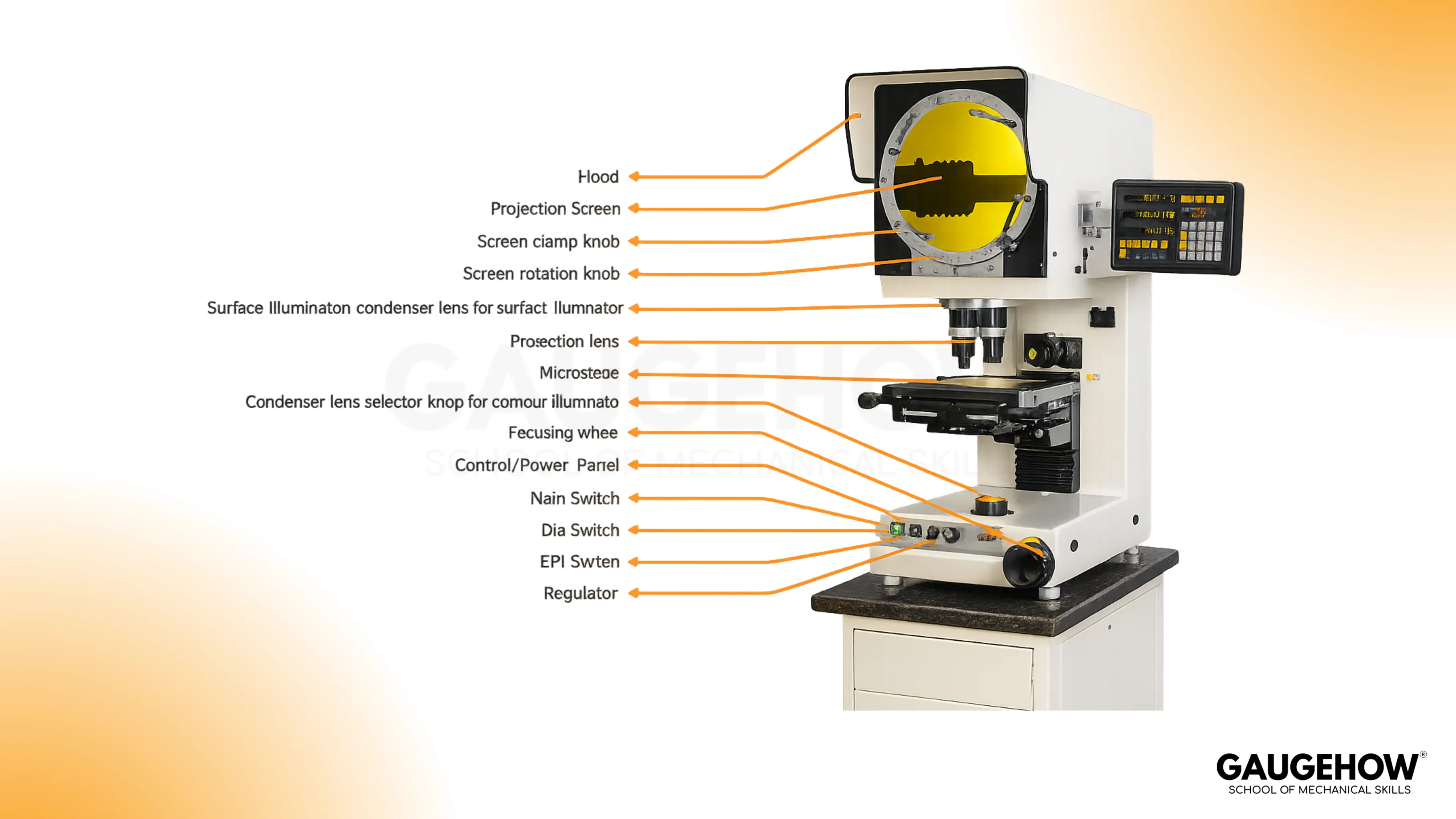
Optical comparator diagram and components
A good optical comparator diagram should make one thing obvious: which components change the measurement and which only change comfort. Illumination, optics, stage behavior, and reference reading method decide whether your result holds up on the next shift.
Components That Change Trustworthiness
Role | Mechanism | Shifts Your Result When… | Common Symptom | Practical Fix |
Illumination | Creates edge contrast | Mode or intensity changes | Fuzzy or “thick” edge | Stabilize lighting, clean optics, re-select mode |
Objective optics | Sets magnification fidelity | Lens choice or condition changes | Drifts across the field | Verify magnification, avoid edge-of-field abuse |
Screen and reading method | Defines how you pick points | Interpretation changes | Two operators disagree | Standardize one rule, train it, audit it |
Stage and X–Y system | Moves the part frame | Backlash and approach vary | Different results by direction | Always approach from the same direction |
Fixturing | Holds datum and angle | Part tilt or shift occurs | “Profile error” appears | Improve clamping and datum strategy |
Telecentric Optical System
A telecentric optical system keeps magnification effectively constant across the field, which reduces measurement error caused by perspective and small height differences.
That matters when you measure near the edge of the screen, compare wide profiles, or want fewer “it passes in the center but fails at the corner” arguments.
Optical System Varieties
Optics Variety | Best For | Tradeoff You Should Expect |
Simple optics | Basic viewing, quick checks | More distortion toward the field edges |
Corrected optics | General measurement across a moderate field | Still not immune to perspective and setup effects |
Fully corrected optics | Better fidelity over more of the screen | Higher cost, still needs verification of habits |
Telecentric optics | Consistent magnification across the field | Cost and system complexity rise |
Quick Symptom Triage
If the edge is unstable, fix illumination and cleanliness first. If the measurement shifts by stage approach direction, treat it as stage behavior, not part variation. If a mismatch happens mainly near the outer screen region, verify magnification and field behavior before blaming the process.
Different Types Of Profile Projector
Different configurations exist because parts behave differently on the stage. The best setup is the one that holds your part stable, gives a repeatable datum, and produces a consistent edge image.
Profile (Contour) Setup
Silhouette illumination is the workhorse for outlines, radii, thread forms, and stamped profiles. It is fast and intuitive, but it depends heavily on edge contrast and focus discipline.
Surface (Reflected Light) Setup
Reflected illumination helps when you need to view surface features, such as scratches, burrs, or shallow features that do not present a clean silhouette. Glare management matters here, so lighting angle and filtering become your controls.
Vertical Setup
A vertical arrangement is usually better for flat parts that can sit stably on a glass stage. Gaskets, shims, and thin stamped parts often become easier because gravity helps, not hurts.
Horizontal Setup
A horizontal arrangement is usually better for heavier, taller, or awkward parts, where side viewing and more robust support give stability. Shaft-like parts and heavier components often fit more naturally here.
Selection Cues Table
Your Part Reality | Usually Pick | Because |
Flat, light, easily seated | Vertical | Stable placement and easier datum control |
Heavy, tall, or irregular | Horizontal | Better support and less tendency to rock |
Outline is the functional requirement | Contour illumination | Clean silhouette enables reliable comparison |
Surface condition is the concern | Reflected illumination | You can reveal defects that silhouettes hide |
🔧 Trusted by 23,000+ Happy Learners
Industry-Ready Skills for Mechanical Engineers
Upskill with 40+ courses in Design/CAD, Simulation, FEA/CFD, Manufacturing, Robotics & Industry 4.0.
Best Uses And Practical Workflows
This tool earns its keep when the decision is profile-based and time matters. The best uses are the ones where non-contact, visual comparison gives you speed without sacrificing control.
Profile Checks On Machined Parts
Radii blends, groove geometry, small angles, and transitions are strong candidates when the functional requirement is the edge-defined outline.
Thread Form Screening
The silhouette can reveal flank angle behavior and form issues that are hard to communicate with a single contact reading. Keep alignment tight and interpretation consistent.
Cutting Tool Profile Confirmation
Tool geometry is performance. A magnified, repeatable view helps confirm form and edge geometry without risking a contact-induced nick.
Overlay Charts And Chart Gages
Overlay charts and chart gages are a fast way to run go or no-go profile decisions in production. They work well when you standardize alignment, control the overlay condition, and verify the overlay against a known reference on a routine cadence.
Advantages of Optical Comparator
The Advantages of the optical comparator are listed below:
Fast Profile Inspection
Part outlines appear on screen within seconds. Quick alignment and direct comparison reduce review time during first-piece approval and in-process checks.
Non-Contact Measurement
Projected images support profile review without probe force. Thin sections, soft materials, and finished surfaces stay free from contact marks during inspection.
Clear Edge Visibility
Magnified projection makes edges easier to study. Radii, chamfers, tapers, slots, and formed shapes become clearer during review and approval.
Simple Comparison Workflow
Overlay charts and screen references support direct profile comparison. Inspection teams can move from setup to decision without heavy programming effort.
Good Accuracy For Profile Work
Optical comparison works well for outline-based checks. Angle review, form verification, and contour approval become easier during drawing release and sample validation.
Useful For Small Parts
Tiny features become larger and easier to inspect. Small punches, stamped parts, threads, and fine profiles can be reviewed with better control.
Lower Operator Influence
No measuring force enters the checking process. Better repeatability follows because hand pressure does not change the reading from one review to another.
Benefits, Risks, And Mitigations
Benefit | Why It Helps | Risk | Mitigation Habit |
Non-contact inspection | Less part deflection | Part stability becomes critical | Fixture well, minimize vibration |
Fast profile comparison | Throughput improves | Operator interpretation varies | Lock one edge rule and train it |
Visual confirmation | Easier disposition decisions | Overconfidence in the picture | Verify magnification and stage behavior |
Strong on complex outlines | Profiles become obvious | Edge quality can lie | Control lighting, focus, and cleanliness |
Verification
Before you accept any reading, the working principle of the optical comparator must be backed by checks that match your risk level. A simple routine covers most of the real-world failure modes:
Magnification check at the lens you are using
X–Y stage behavior and linearity check over typical travel
Angle reference check for any angular measurements or overlays
Limitations And Tradeoffs
A large field of view is convenient, but it can dilute resolution and make edge interpretation harder, especially near the extremes of the image.
Surface viewing can also be more difficult than silhouette work because glare, finish, and contrast can create edges that look real but are not measurement-stable. These are not reasons to avoid the tool; they are reasons to control setup and verification.
Conclusion
Use a profile projector when the functional requirement is an edge-defined outline, and you need fast, repeatable decisions with minimal part handling. Put your discipline into datum choice, illumination control, and verification, because that is where trust is won or lost. Done right, the Optical Comparator becomes a consistent production tool rather than an inspection bottleneck.
FAQs
1. Accuracy Expectations On A Profile Projector
Accuracy depends on optics, verification habits, and edge stability more than on magnification alone. If you are auditing the optical comparator working principle, focus on repeatable lighting, a single edge interpretation rule, and a verification routine that matches your tolerance risk.
2. Telecentric Optics Worth It In Daily QA Work
Telecentric optics usually pay off when you measure across a wide field, run overlays near the screen edges, or want fewer perspective-driven disagreements. The benefit is consistency across the field, not “more zoom.”
3. Vertical Versus Horizontal Setup Choice
Choose the setup that makes fixturing and datum alignment easiest. Flat parts that seat naturally tend to favor vertical arrangements, while heavier or awkward parts often behave better in horizontal arrangements.
4. Overlay Charts And Chart Gages, Where They Fit Best
They fit best in production screening, first-article confirmation, and repeat checks, where pass or fail is based on outline match. Keep overlays controlled, stored correctly, and verified on a routine schedule.
5. Contact Comparator Versus Projection Comparator
A mechanical optical comparator can be the better choice when the feature is not optically accessible, the environment is harsh, or you need amplified deviation at a contact point. Projection wins when the decision is profile-based, and the visible edge defines function.


