What is a Vernier Caliper? Parts & Least Count Explained

A vernier caliper is a precision measuring tool used to measure outside size, inside size, and depth. It measures OD (Outer Diagram), ID (Internal Diagram), and depth using jaws and a depth rod.
It achieves fine readings by aligning a vernier scale mark with the main scale. Least count is the smallest step the caliper can reliably show.
Least count depends on the scale design, so don’t assume a single value.
What is a Vernier Caliper? It helps you take repeatable measurements that a ruler can’t. In a few minutes, you’ll be able to identify the measuring faces, find the least count on your tool, read the scale cleanly, and handle zero error without guesswork.
Practical flow stays steady: Start with the layout and parts, then lock in least count, then read a measurement, then correct errors, then check accuracy habits that prevent bad numbers.
Vernier Caliper Diagram
The image added below shows a vernier calliper.
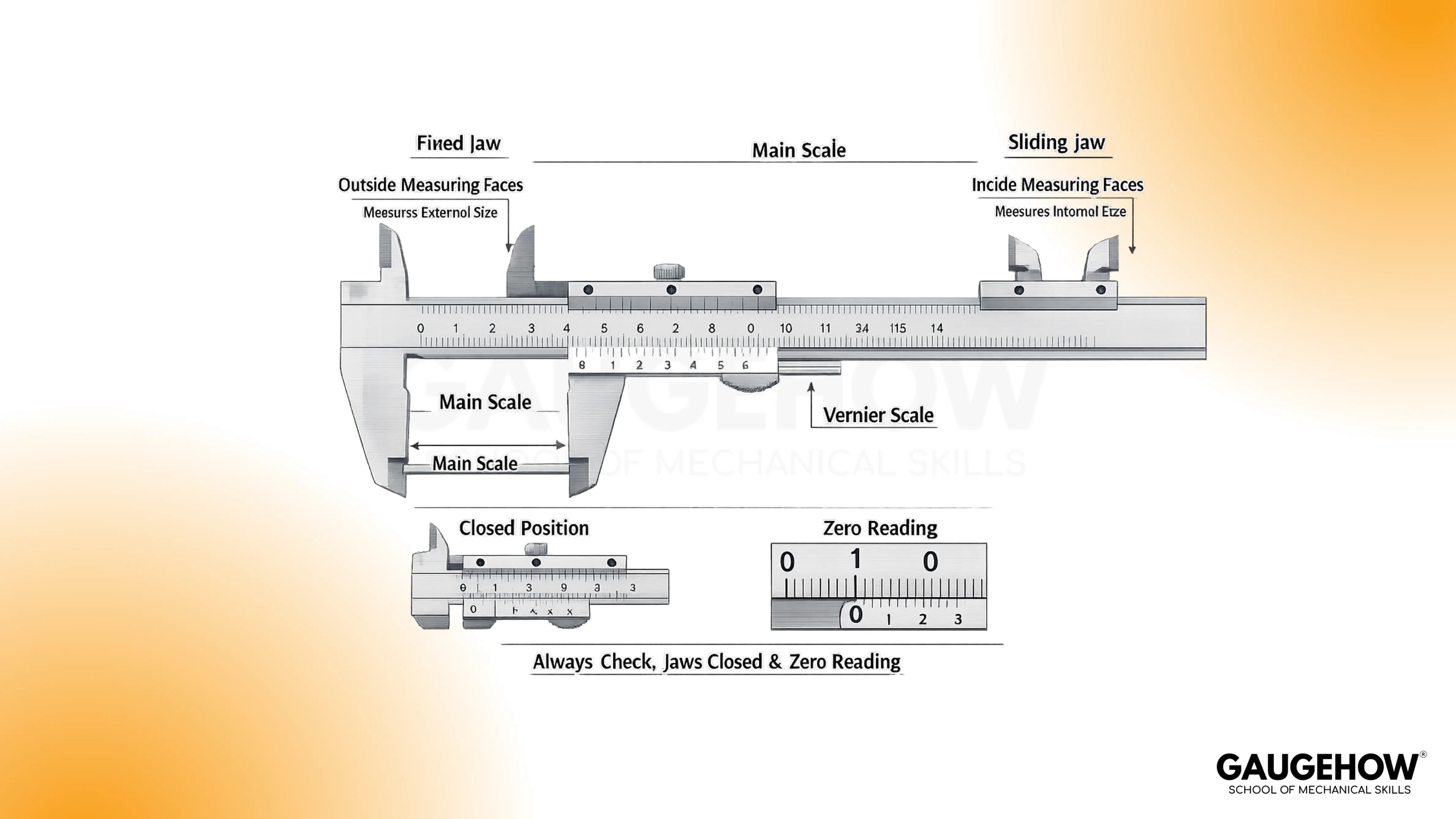
Parts of a vernier caliper
A clear understanding beats memorizing labels. Most mistakes happen because the vocabulary gets learned, but the function stays fuzzy. So group the parts of the vernier caliper by what they do, not what they’re called.
Let's look at the main parts of the Vernier Calliper:
Fixed Jaw
Movable Jaw
Main Scale
Vernier Scale
Lock screw
Thumb screw
Zero adjustment screw
Depth screw
Upper Jaw
Lower Jaw
Locking Screw
Small numbers only help when the meaning is clear. Confusion shows up because people treat the least count as “guaranteed accuracy,” then feel stuck when real readings drift.
So, Vernier caliper least count should be understood as the smallest step the scale can show, while technique and tool condition decide how close you get to the truth.
Least count is easiest to picture as a “scale step size.” In many common calipers, typical values are 0.1 mm, 0.05 mm, and 0.02 mm, depending on the vernier scale design. Reading the value printed on the tool or case is better than guessing.
Conceptually, the vernier works because one vernier division is slightly different from one main scale division. That small difference lets the vernier mark “catch up” and align, and the alignment tells you the fraction. Practically, the formula you’ll use is:
Reading = MSR + (VSR × LC)
Where MSR is the main scale reading, and VSR is the vernier division that aligns best.
A quick example makes it real. Suppose:
MSR is 12.0 mm
Aligned vernier line is 6,
LC is 0.02 mm.
The add-on is 6 × 0.02 = 0.12 mm, so the final reading is 12.12 mm.
🔧 Trusted by 23,000+ Happy Learners
Industry-Ready Skills for Mechanical Engineers
Upskill with 40+ courses in Design/CAD, Simulation, FEA/CFD, Manufacturing, Robotics & Industry 4.0.
How to Read a Vernier Caliper
Messy reading usually comes from a missing routine. That happens because the eye jumps between scales, and the hand squeezes instead of settling.
So follow one mental model once, then apply it every time: Z-M-V-C, meaning Zero check, Main scale, Vernier match, Correction.
Start by closing the jaws and confirming the zeros line up. Clamp the part lightly and read MSR just left of the vernier zero.
Find the vernier line that aligns perfectly with a main scale line, that is,s VSR. Multiply VSR by the least count and add it to MSR, then write the result in consistent units.
Clean contact faces before measuring.
Use light, repeatable touch, not squeezing.
Avoid jaw tilt on edges and curved parts.
Read at eye level to reduce parallax.
Bad touch equals bad number, even when the scale looks perfect.
Accuracy vs Least Count
False confidence happens when resolution is mistaken for accuracy. That happens because the caliper can display a small increment, yet still be off due to wear, dirt, or technique.
So treat the least count as what you can read, and accuracy as how close that reading is to the true size.
If you’re still asking, What is a Vernier Caliper in real work terms, it’s a fast instrument for consistent checks, not a guarantee of micron-level truth.
When the number truly matters, compare against a known standard, a gauge block, or a trusted reference part. That quick comparison tells you whether the tool is behaving or drifting.
Zero Error and Correction
Annoying disagreements often start at zero. That happens because the jaws look closed, yet the scale doesn’t read zero. So zero error should be treated as a correction workflow, not a definition.
First, close the jaws gently and note the offset, if any.
Then, measure the part normally using the same light touch. Finally, apply the correction with the correct sign, because direction matters and consistency matters more than speed.
A simple habit protects you: close the jaws again after the measurement and confirm the error didn’t drift.
Uses and Best Practices
Every use maps to a measuring face. Outside jaws measure external widths, thicknesses, and shaft diameters when the jaws sit flat and square.
Inside jaws measure internal diameters when you keep the tool centered and avoid tilting. Depth rods measure hole depth and step depth when the caliper body sits flush on the reference surface.
Gentle care keeps readings stable. Wipe the jaws, avoid dropping the tool, and don’t store it clamped tight.
Calmly, lock the slider before lifting the tool away from the job, because small slips create silent errors.
Common Mistakes to Avoid
Wrong numbers usually come from familiar habits, not bad math. That happens because contact errors hide until you compare measurements. So treat these as the first things to eliminate.
Parallax reading from an angled view.
Using the wrong jaw for OD, ID, or depth.
Tilting the tool during outside or inside measurement.
Over-squeezing and flexing the part or tool.
Ignoring zero error and skipping correction.
Measure once, rotate the part slightly, measure again, and the result should stay stable.
FAQs
What’s the fastest way to get consistent readings?
A reliable technique is more important than speed. Use light contact, lock the slider, then read at eye level. Confirm repeatability with a second reading after a small reposition. Consistency usually improves immediately when squeezing stops.
How do I measure internal diameter without under-reading?
Centering matters because inside jaws can touch a chord instead of the true diameter. Gently “rock” the caliper to find the maximum reading, then lock and read. Repeat once more to confirm the same maximum shows up again.
Why does my measurement change when I clamp harder?
Extra force can flex the caliper, compress soft parts, or cause jaw tilt. Light touch produces more repeatable results because it reduces deformation and sliding. Aim for contact, not pressure, then verify with a second read.
When should I use a micrometer instead of a caliper?
Micrometers are better for tighter tolerances and small ranges where higher repeatability is needed. Calipers are excellent for quick checks, mixed measurements, and general fitting. If the tolerance is very tight, switch early instead of arguing with a caliper.
Do digital calipers remove reading errors?
Digital displays remove vernier alignment, but contact errors remain. Dirt, tilt, over-squeezing, and poor zeroing still create bad numbers. Treat the display as convenient, not magical, and keep the same light-touch routine.


