Shared Topology In SpaceClaim: Merge, Share, Group
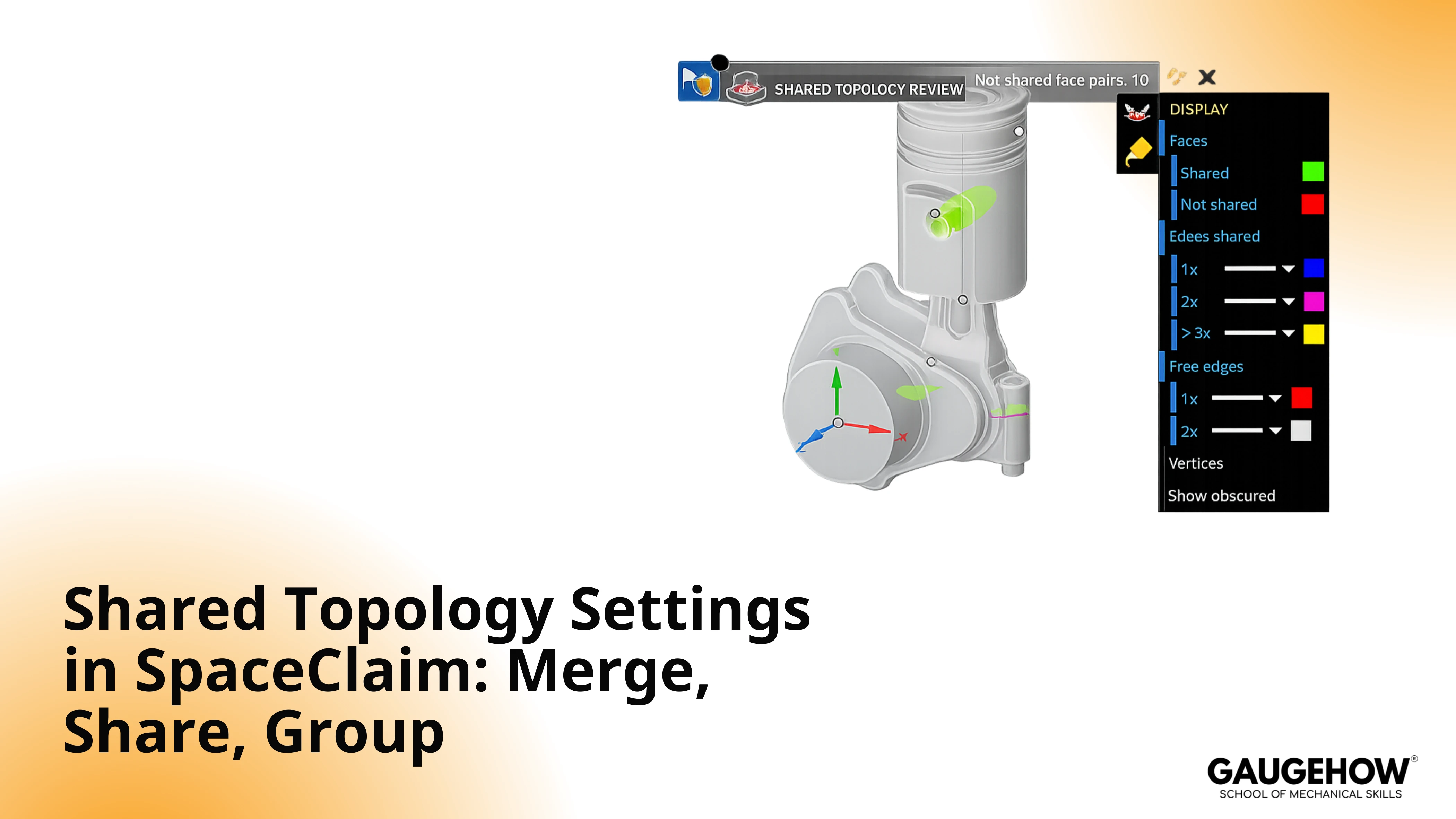
SpaceClaim shared topology is a transfer behavior that can carry topological connectivity across contacting boundaries into the downstream model. Inside a single configured component, it can produce a matched interface topology between participating bodies.
Outside that component scope, interface linkage remains absent, and interfaces stay independent.
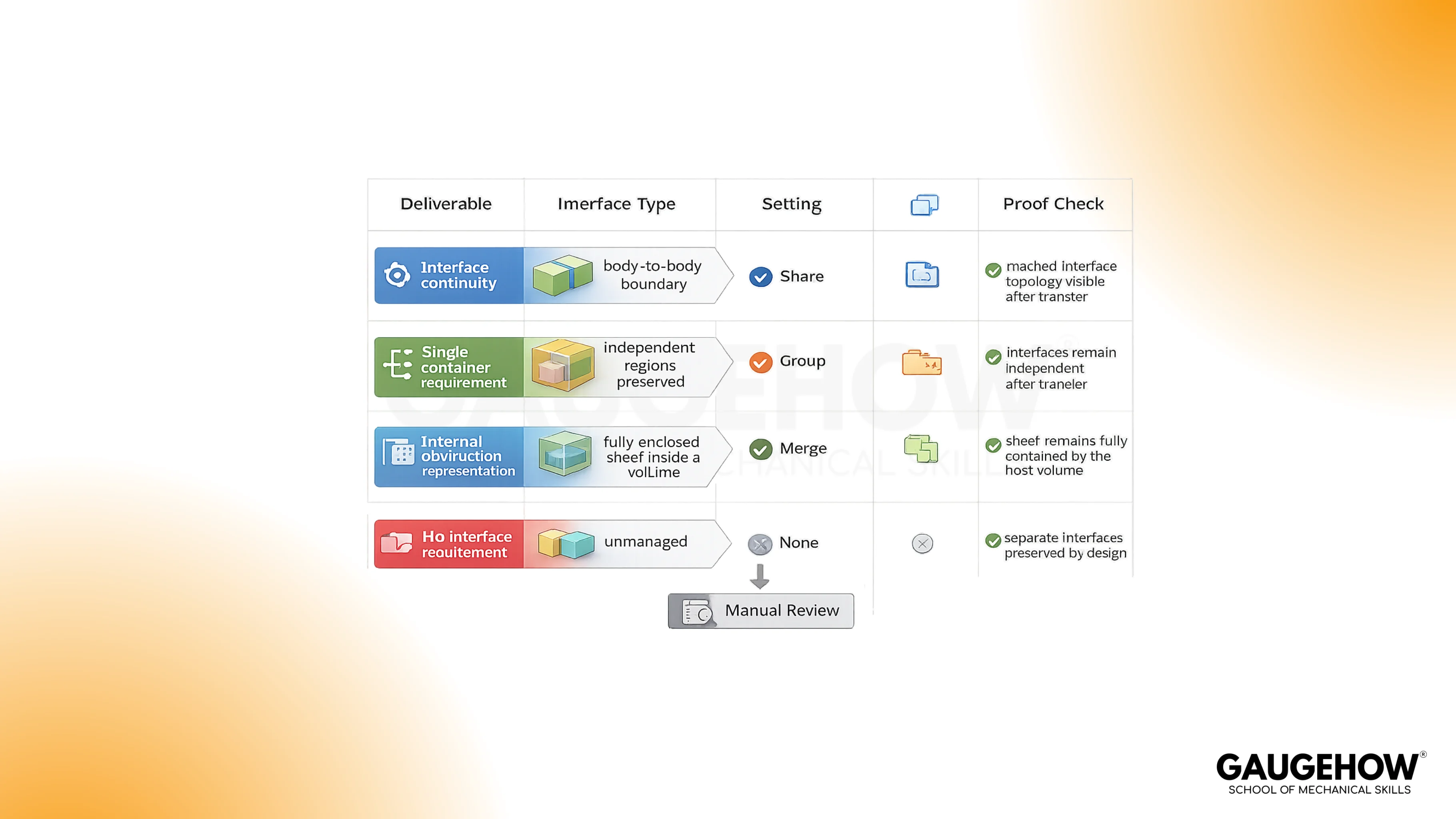
Merge targets embedded internal sheets, Share produces matched interfaces under one part container, and Group packages bodies without interface linkage.
DISP Rule
Shared Topology Merge Vs Share Vs Group
The decision becomes stable when DISP stays first, and menu names stay second. One body can look “connected” visually while still behaving independently after transfer.
Comparison Table: Features, Merge, Share, Group
Features | Merge | Share | Group |
Best Fit Deliverable | Embedded internal sheet inside volume | Matched interface topology across intended boundaries | Single container, interfaces independent |
Interface Behavior | Embedded-sheet behavior only under full enclosure | Matched interface topology at intended contacts | Interface linkage remains absent |
Container Result | Single container with multiple bodies | Single container with multiple bodies | Single container with multiple bodies |
Pass Condition | Sheet perimeter fully enclosed by host volume | Shared boundary shows a matched interface on both sides | Interfaces remain separate while one container exists |
What Is SpaceClaim Shared Topology
Shared topology is best treated as a controlled connectivity rule during export, not as a geometry operation. It governs whether contacting boundaries arrive downstream as matched interface topology or as independent regions that require contact handling.
Scope boundary: Behavior applies only to bodies grouped under the configured component. Observable output: matched interface topology appears only where the setting and placement allow it.
Merge Option Meaning
Merge fits internal sheet bodies used as obstruction representations inside a host volume region.
Scope boundary: Merge behavior remains valid only when the internal sheet stays fully enclosed along its perimeter.
Observable output: The internal sheet participates as an embedded obstruction without breaking host containment.
Proof check: Enclosure remains complete.
Merge Option Uses
Internal resistance sheets inside a fluid region
Idealized screens or partitions represented as internal sheets
Nested containment chains where the enclosure remains complete at every level
Share Option Meaning
Share creates matched interface topology across intended contacting boundaries and packages the bodies under one part container for downstream work.
Scope boundary: Only bodies under the configured component participate.
Observable output: Intended interface boundaries align and behave as a matched interface set after transfer.
Proof check: Matched interface topology appears at the specified interface only.
Share Option Uses
Flange contacts, housings, and split solids requiring node matching.
Intersections where interface alignment is required downstream.
Reduced the contact definition workload when interfaces are meant to behave as one matched boundary set.
Micro-Example
Two solids share a flange interface in Mechanical. Share selection can reduce contact setup from multiple face-pairs to zero explicit pairs because the interface arrives as a matched boundary set.
Audit: The interface boundary shows matched topology on both sides.
PASS: No manual contact pairs required for that interface.
Group Option Meaning
Group packages bodies under one component for transfer while leaving the interface linkage absent.
Scope boundary: Grouping changes container structure, not boundary connectivity.
Observable output: Bodies appear under one container node while interfaces remain independent.
Proof check: Interfaces remain separate even inside the same container.
Group Option Uses
Single deliverable container with independent interfaces.
Separate meshing intent per body while keeping one delivered structure.
Versioned projects where grouping behavior is desired without interface connectivity.
Conformal Mesh Shared Topology
A conformal mesh shared topology outcome requires interfaces that arrive downstream with matched boundary connectivity, so node matching becomes natural at the interface.
Scope boundary: This outcome depends on correct component placement plus clean interface classification. Observable output: the interface behaves as a matched boundary set rather than two independent regions.
Proof check: Boundary alignment is visible at the interface after transfer.
Share Topology Baffles
The phrase share topology baffles usually points to internal sheet use cases where Merge is the correct intent.
Scope boundary: Internal sheets must stay enclosed inside the host volume for merge behavior to remain valid.
Observable output: The obstruction sheet exists fully inside the volume domain.
Proof check: No sheet perimeter crosses the host boundary.
Interface Outcomes After Transfer
Outcome language keeps the discussion practical.
Share: Matched interface topology at intended boundaries under one part container
Group: Single-part container with multiple bodies; interface linkage remains absent
Merge: Internal sheet participates only under complete enclosure
None: Independent bodies and independent interfaces by design
Short distinction: shared-topology connectivity modifies downstream interface behavior; boolean-merged solids modify the geometry itself. Mesh results can diverge because the underlying mechanism differs.
Component Placement Rules
Placement determines participation.
Configure the component property first, then place participants under that component.
Isolate bodies requiring independence outside the sharing scope.
Avoid a broad parent scope when only a subset requires sharing behavior.
Use component boundaries as the control surface for sharing intent
Observable audit: component tree shows only intended bodies under the configured component.
Unsupported Geometry Boundaries
Boundary recognition prevents non-repeatable outcomes.
Supported categories include:
Clean contacting boundaries intended to behave as matched interfaces
Intended surface intersections requiring consistent interface alignment
Fully nested containment where bodies remain fully inside host bodies
Fully enclosed internal sheets inside a host volume chain
Out-of-scope categories include:
Partial volume overlaps without a clear interface boundary definition
Internal sheets crossing outside the host volume boundary
Mixed conditions where the enclosure breaks along the perimeter
Audit: Geometry classification fits one category without partial overlaps.
PASS: Clear interface classification.
FAIL: Partial overlap or broken enclosure exists.
Version Behavior Notes
Later releases formalize the group as packaging across body types under a component. Older databases opened in newer releases can show behavior shifts when legacy hierarchy planning was loose. Audit remains consistent: hierarchy scope and downstream container behavior.
Beam Transfer Edge Cases
Beam networks under one component can arrive as one beam body with multiple edges, depending on connectivity and section matching. Audit: downstream beam structure matches intended connectivity and edge count.
PASS: expected beam body and edge structure visible.
FAIL: unexpected splits or missing intersection edges.
Proof Checks Before Meshing
Third and final required use: SpaceClaim shared topology selection is incomplete until proof checks are observable in the downstream model tree or interface boundaries.
Proof Checklist
The component node shows the intended setting value
The component tree contains only intended participant bodies
Merge: internal sheet perimeter stays fully enclosed by host volume
Share: matched interface topology visible at intended boundaries
Group: single container visible while interfaces remain independent
Troubleshooting Mini-Table
Common Mistake | Downstream Cost | Outcome | Pass Condition |
Share selected, interfaces stay separate | Contact setup + re-mesh cycles | Independent interfaces persist | Both bodies sit under one configured component |
Sharing spreads beyond intent | Unwanted interface matching + re-validation | Extra bodies receive sharing behavior | Only intended bodies remain under the sharing scope |
Merge fails on internal sheet | Geometry edits + export repeats | Enclosure rule violated | No sheet perimeter crosses the host volume boundary |
The group used an expecting node matching | Nonconformal interface + manual contacts | Packaging occurs without linkage | The interface requirement does not call for node matching |
Failure-Mode Reality Check
Mode | Cost | Audit | Pass |
Share Scope Too Broad | Cleanup | Tree | Intended bodies only |
Group For Node Match | Contacts | Interface | Matched boundary present |
Merge Broken Enclosure | Rework | Enclosure | Fully enclosed sheet |
Benefits And Limitations
Benefits:
Deliverable-first selection reduces downstream cleanup
Audit-style pass conditions replace guesswork
Component boundary planning controls sharing scope reliably
Contact setup workload reduces when matched boundaries are the intended outcome
Limitations:
Partial overlaps and broken enclosures require geometry cleanup for a predictable result.s
Broad hierarchy scope can override intended isolation
Visual similarity of solids is not a reliable proxy for boundary connectivity
Frequently Asked Questions
Why Interfaces Stay Separate After Share
Share participation requires both bodies under the same configured component and a clean intended contacting boundary. Separation after transfer usually indicates component separation or scope placement error. Check component tree membership, then audit boundary alignment.
When Merge Is Valid For Baffles
Merge fits internal sheet obstructions only under a complete enclosure by a host volume. Any sheet perimeter crossing outside the host boundary invalidates the condition. Audit sheet perimeter relative to host volume limits before export.
How Group Differs From None In Newer Versions
Group packages bodies into one container while leaving the interface linkage absent. None preserves independence without an enforced packaging structure. Audit downstream container structure and verify interface boundaries remain independent for Group and None.
How Sharing Gets Blocked Across An Assembly
Isolation comes from component boundaries and hierarchy. Keep independent bodies outside configured components and avoid parent scopes that include them.
Why Mesh Differs Between Shared Connectivity And Boolean-Merged Solids
Shared connectivity changes interface behavior after transfer; boolean merging changes geometry topology. The mesh can differ because one modifies boundary connectivity and the other modifies solids. Audit boundary alignment versus fused-body topology, then match to deliverable intent.
CAD-CAM-CAE Work Platform
Find or Post CAD, CAM and CAE freelance projects, full-time jobs and Internships.
GaugeHow is the platform built for core engineering work. Whether you need a freelancer for a CAD project, a full-time hire, or an engineering intern,post it here and get matched with the right person.


