Engineering Mechanics
What is Engineering Mechanics? Everything You Need to Know
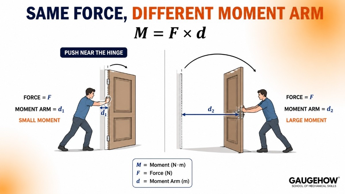
Push a door near the hinge and it barely moves. Push it near the handle and it swings open easily. Same hand, same push, completely different result.
That one observation is the seed of an entire subject. Engineering Mechanics is the science that explains why the position of a force matters, why a ladder slips, why a crane tips over, and why a bridge stands still for a hundred years.
This guide answers the question properly. You will learn what engineering mechanics actually is, how it splits into branches, the real difference between statics and dynamics, the types of forces you will meet, how SI units and dimensions keep your answers honest, what a factor of safety is, and where the subject shows up in real engineering jobs.
What is Engineering Mechanics?
Engineering Mechanics is the study of how forces act on bodies, and what those forces do to the body: keep it still, move it, spin it, or break it.
Split the name in two and it becomes obvious:
Mechanics is the physics of force and motion.
Engineering means using that physics to design real things that must not fail.
Think of a bicycle. Your weight presses down on the seat. The chain pulls the rear wheel. The brake pad rubs against the rim. Every one of those is a force, and the frame has to survive all of them at once. Engineering mechanics is how you predict that survival on paper, before anyone builds anything.
Why the subject exists
Physics states a truth. Engineering mechanics turns that truth into a number you can put on a drawing.
A physicist says the ladder will slip if friction is too small. An engineer says the ladder slips below 63 degrees, so keep it above 70 degrees, and prints that on the manual.
Where it is used
Sizing a beam in a factory shed so it does not sag under a hoist.
Choosing bolt size for a machine frame that vibrates all day.
Checking that a car does not roll over while cornering.
Branches of Mechanics
Mechanics is a large tree, and engineering mechanics sits on one branch of it. Knowing the map prevents a lot of confusion later.
Mechanics splits into three families:
Mechanics of Rigid Bodies: bodies that do not change shape. This is the classic engineering mechanics taught in the first year.
Mechanics of Deformable Bodies: bodies that stretch, bend and twist. This grows into Strength of Materials.
Mechanics of Fluids: liquids and gases. This grows into Fluid Mechanics.
Rigid body mechanics then splits into two, which brings us to the most asked question in the subject.
BranchDeals withWhat it becomes laterRigid body: StaticsBodies at restStructural analysis, machine designRigid body: DynamicsBodies in motionTheory of machines, vibrationsDeformable bodyStress, strain, bendingStrength of MaterialsFluid mechanicsPressure, flow, dragFluid Mechanics, CFD
If simulation is where you want to end up, the deformable body branch is the one that leads to FEA. The FEA with ANSYS course picks up exactly where the rigid body assumption stops being good enough.
Difference Between Statics and Dynamics
Here is the difference between statics and dynamics in one line: statics deals with bodies that are not accelerating, dynamics deals with bodies that are.
Note the wording. Not "not moving". Not accelerating.
A parked car is a statics problem. A car cruising at a steady 60 km/h on a straight road is also a statics problem, because its acceleration is zero. The moment it brakes, turns or speeds up, it becomes dynamics.
An everyday example
Statics: you stand still on a weighing scale. Your weight pushes down, the scale pushes up, the two are equal, nothing moves.
Dynamics: you stand on the same scale inside a lift. The lift accelerates upward and the reading jumps. That extra reading is dynamics.
The two governing statements
Statics: ΣF = 0 and ΣM = 0
ΣF = sum of all forces acting on the body, in newtons (N)
ΣM = sum of all moments, or turning effects, about any point, in newton metre (N·m)
The symbol Σ (sigma) simply means "add them all up"
Dynamics: ΣF = m × a
m = mass of the body, in kilograms (kg)
a = acceleration, in metre per second squared (m/s²)
Statics is really just the special case of dynamics where a = 0. One subject, two moods.
FeatureStaticsDynamicsAccelerationZeroNot zeroCore equationΣF = 0, ΣM = 0ΣF = maTypical problemBeam reactions, truss forces, ladder frictionProjectile, lift, car on a curve, vibrationReal design useBuildings, brackets, bolted jointsEngines, robot arms, suspensions
Rigid Body vs Deformable Body
A rigid body is a body we pretend cannot change shape. The distance between any two points inside it stays fixed, no matter how hard you push.
A deformable body is the honest version. It stretches, bends, compresses and eventually breaks.
The analogy
Push a steel almirah across the floor. It does not visibly bend, so treating it as rigid is fine. Now hang a heavy bag from the middle of a long steel shelf. It sags. That sag is deformation, and pretending it is zero would be a lie.
Why we still assume rigid
Because it works, and it is simpler. In a typical steel beam the deflection is a few millimetres over a span of several metres. That is far too small to change the direction or line of action of the forces, so the force calculation stays valid.
The real design workflow looks like this:
Assume the body is rigid.
Find the forces and support reactions using engineering mechanics.
Feed those forces into strength of materials to find stress and deflection.
Only then decide whether the part is thick enough.
Engineering mechanics is step 2. Every later subject depends on you getting it right.
Scalar and Vector Quantities
A scalar has size only. A vector has size and direction.
Ask someone how far the market is and they say two kilometres. That is a scalar. Ask them where it is and they say two kilometres north. That is a vector.
TypeMeaningExamplesScalarMagnitude onlyMass, time, temperature, speed, work, energy, distanceVectorMagnitude and directionForce, weight, velocity, acceleration, moment, displacement
Force is a vector. That single fact is why engineering mechanics is not just arithmetic. A 10 N push to the left and a 10 N push to the right add up to zero, not 20 N.
A vector is written in bold (F) or with an arrow above it. Its magnitude alone is written as F or |F|.
Why it matters in practice
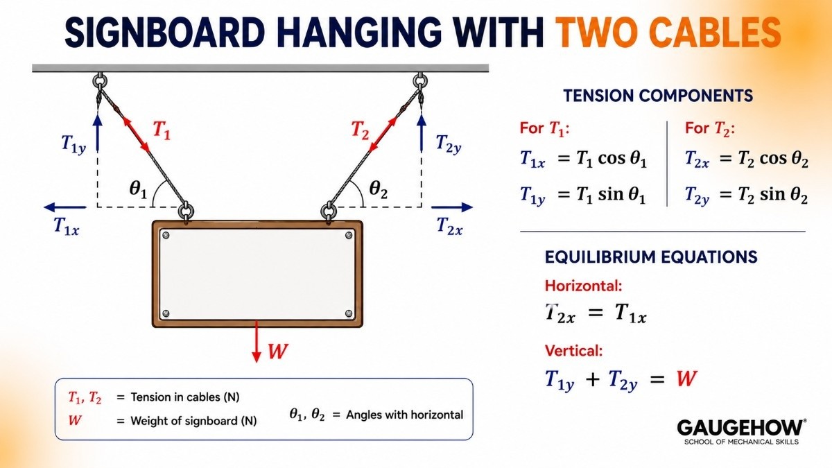
Two cables hold a signboard at different angles. You cannot simply add the two tensions. You must break each one into horizontal and vertical parts first. That splitting is called resolution of forces, and it is one of the first skills every mechanics student builds.
Types of Forces in Engineering Mechanics
A force is a push or a pull. In SI units it is measured in newtons (N). One newton is the force that gives a 1 kg mass an acceleration of 1 m/s².
Here are the types of forces in engineering mechanics you will meet again and again.
Grouped by how they act
Contact forces need physical touch: normal reaction, friction, applied push, rope tension.
Body forces act without touching: weight caused by gravity, and magnetic force.
Grouped by where they come from
External force: applied from outside the body, such as a load placed on a beam.
Internal force: the force members exert on each other inside a structure, such as tension inside a truss member.
Grouped by how they are spread
Concentrated load (point load): acts at a single point, like a person standing on a plank. Measured in N or kN.
Distributed load: spread over a length or area, like a layer of bricks along a beam. Measured in N/m or kN/m.
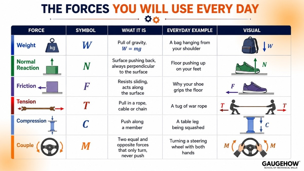
The forces you will use every day
Formula: W = m × g
W = weight in newtons (N)
m = mass in kilograms (kg)
g = acceleration due to gravity = 9.81 m/s²
Worked example
A crate has a mass of 50 kg. Find its weight.
Write the formula: W = m × g
Substitute: W = 50 × 9.81
Solve: W = 490.5 N
The crate weighs 490.5 N, roughly 0.49 kN. Its mass stays 50 kg everywhere in the universe, but its weight would change on the Moon. Mass is a scalar, weight is a vector.
SI Units in Engineering Mechanics
Engineering mechanics is only useful if a number means the same thing to everyone. That is the job of the SI system, the International System of Units.
Three base units carry almost all of mechanics.
QuantitySI base unitSymbolLengthmetremMasskilogramkgTimeseconds
Everything else is built from those three.
QuantityDerived unitSymbolIn base unitsForcenewtonNkg·m/s²Moment / torquenewton metreN·mkg·m²/s²Pressure / stresspascalPaN/m²Work / energyjouleJN·mPowerwattWJ/s
A common trap: kg is mass, not force. Saying "a load of 500 kg" is loose talk. The load is 500 × 9.81 = 4905 N, which is 4.905 kN. Examiners cut marks for this. So do design reviewers.
Dimensions and Dimensional Homogeneity
Dimensions describe what kind of quantity something is, independent of the unit used. The three basic dimensions in mechanics are Mass [M], Length [L] and Time [T].
Force, for example, has dimensions [M L T⁻²]. That stays true whether you measure it in newtons or pounds.
Why this is quietly powerful
Both sides of a correct equation must carry the same dimensions. That gives you a free error check called dimensional homogeneity.
Check ΣF = ma:
Left side, force: [M L T⁻²]
Right side, mass × acceleration: [M] × [L T⁻²] = [M L T⁻²]
Both match, so the equation is dimensionally sound.
If you derive a formula and the dimensions do not match, you made an algebra mistake. Fix it before you plug in numbers.
Unit Conversion
Real problems arrive in mixed units. Data sheets use mm, drawings use m, motors are rated in kW, older catalogues still use kgf. Converting cleanly is a survival skill.
The rule: multiply by a fraction that equals 1.
To convert 5 kN into N: 5 kN × (1000 N / 1 kN) = 5000 N. The kN cancels, the N survives.
Conversions worth memorising:
1 kN = 1000 N
1 kgf = 9.81 N (the force one kilogram of mass exerts on Earth)
1 MPa = 1 N/mm² (this one saves enormous time in stress problems)
1 m = 1000 mm
1 kW = 1000 W
1 tonne = 1000 kg, so a 1 tonne load = 9810 N = 9.81 kN
Worked example
A beam carries a load of 2 tonnes. Express it in kN.
Convert tonnes to kg: 2 × 1000 = 2000 kg
Convert mass to force: W = m × g = 2000 × 9.81 = 19620 N
Convert to kN: 19620 / 1000 = 19.62 kN
Answer: 19.62 kN.
Real Engineering Applications
This subject is not exam furniture. It runs quietly inside almost every object you touched today.
Buildings and bridges: support reactions, truss forces, wind loads.
Cranes and hoists: tipping checks, cable tension, pulley advantage.
Automobiles: braking distance, cornering, suspension travel, rollover limit.
Machine frames: bolt loads, vibration, base plate reactions.
Robotics: the torque each joint motor must produce to hold an arm out straight.
Aerospace: lift, drag and thrust balanced on a wing.
Conveyors and belt drives: belt tension and friction grip.
The Role of Mechanics in Design
Design is not drawing. Design is deciding, and mechanics is what you decide with.
Here is the sequence a design engineer actually follows:
Identify the loads. What pushes, pulls, spins or shakes this part?
Draw a free body diagram. Isolate the part and sketch every force acting on it.
Apply equilibrium. ΣF = 0 and ΣM = 0 give you the unknown reactions.
Find the internal stress. Strength of materials now takes over.
Compare with material strength. Steel yields at a known stress. Are you below it?
Apply a factor of safety. Then choose the final size.
Skip step 1 or step 2 and everything after it is confidently wrong. CAD will still draw a beautiful part that fails. If you are heading into a design role, the Design Engineer career track shows how this sequence maps onto the actual job.
Factor of Safety Basics
Nature does not read your assumptions. Materials vary, loads spike, someone overloads the lift. So engineers build in a cushion, called the factor of safety (FoS).
Formula: FoS = Failure load / Working load
Or in stress terms: FoS = Failure stress / Allowable stress
Failure load is the load at which the part actually gives way, in N.
Working load, also called the design or allowable load, is what we permit in service, in N.
FoS has no unit. It is a pure ratio.
Example
A rope snaps at 5000 N. You only ever lift 1000 N with it.
FoS = 5000 / 1000 = 5
The rope is five times stronger than it needs to be. That five absorbs frayed strands, sudden jerks, and the person who lifts a bit more than he should.
Typical values
ApplicationTypical FoSAircraft structures (weight critical, tightly controlled)1.5 to 2General machine parts2 to 4Lifting equipment, cranes, ropes4 to 8Uncertain loads or brittle materials5 to 10
A higher FoS means safer, heavier and costlier. A lower one means lighter, cheaper and closer to the edge. Choosing it well is engineering judgement, and it starts with a correct force calculation.
Engineering Mechanics Syllabus
Most universities follow the same engineering mechanics syllabus, whatever the wording on the paper. Here is the standard structure.
Foundations
Introduction, branches of mechanics, SI units, dimensions
Vectors: unit vectors, dot product, cross product, direction cosines
Force systems: characteristics of force, principle of transmissibility, moments, couples
Resolution and composition of forces: parallelogram law, triangle law, polygon law
Statics
Equilibrium of particles: free body diagrams, Lami's theorem
Moments and couples: principle of moments, Varignon's theorem, force couple systems
Equilibrium of rigid bodies: roller, pin and fixed supports, support reactions
Friction: laws of friction, angle of friction, angle of repose, belt and screw friction
Centroid and centre of gravity, composite sections
Moment of inertia: parallel axis and perpendicular axis theorems, radius of gyration
Virtual work
Trusses: method of joints, method of sections, zero force members
Beams: shear force and bending moment diagrams
Dynamics
Kinematics of particles: distance, displacement, velocity, acceleration, projectile motion
Kinetics of particles: Newton's second law, connected bodies
Work, power and energy: work energy principle, conservation of energy
Impulse and momentum: impact, coefficient of restitution
Circular motion: centripetal and centrifugal force, banking of roads
Basics of mechanical vibrations: free and forced vibration, damping, resonance
Statics comes first for a reason. Every dynamics problem still needs the free body diagram skills you build in statics.
Engineering Mechanics Formula Sheet
Keep this engineering mechanics formula sheet next to you while solving problems. These are the core relations the whole subject rests on.
Conversions
1 kN = 1000 N
1 kgf = 9.81 N
1 tonne load = 9.81 kN
1 MPa = 1 N/mm²
1 m = 1000 mm
Careers That Run on Engineering Mechanics
Engineering mechanics is a gate subject. Almost every mechanical and civil career walks through it.
Design Engineer: sizes parts from calculated loads. Usually built alongside a CAD tool such as SolidWorks or Fusion 360.
CAE / Simulation Engineer: feeds forces and boundary conditions into FEA software. If the hand calculation is wrong, the beautiful colour plot is wrong too. See the CAE Simulation Engineer track.
Structural or Civil Engineer: beams, trusses and foundations, which is pure statics.
Automotive and EV Engineer: braking, suspension, cornering, battery pack mounting loads.
Robotics and Automation Engineer: joint torque, payload limits, gripper force.
Maintenance and Plant Engineer: why a shaft failed, why a foundation bolt keeps loosening.
Automating repetitive force calculations is a strong differentiator early in a career, which is why many engineers pair mechanics with the Python for Mechanical Engineers course.
For exams, GATE, PSU, ESE and almost every campus interview open with mechanics questions. You can drill those patterns on the GaugeHow Interview Q&A Hub and the practice test section.
FAQ
Q: What is engineering mechanics in simple words?
A: It is the study of forces acting on a body and what those forces do to it. If the forces balance, the body stays still, and that is statics. If they do not balance, the body accelerates, and that is dynamics. Engineers use it to make sure structures and machines carry their loads without failing.
Q: What is the difference between statics and dynamics?
A: Statics studies bodies with zero acceleration, using ΣF = 0 and ΣM = 0. Dynamics studies bodies with non zero acceleration, using ΣF = ma. A parked car and a car cruising at constant speed are both statics problems. A braking or turning car is a dynamics problem.
Q: What are the types of forces in engineering mechanics?
A: The main ones are weight, normal reaction, friction, tension, compression and couples. They are also grouped as contact forces versus body forces, external versus internal forces, and concentrated point loads versus distributed loads measured in N/m.
Q: Is engineering mechanics hard?
A: It is not hard, but it is unforgiving. Almost every mistake comes from a wrong free body diagram or mixed up units, not from difficult mathematics. Draw the diagram carefully, keep everything in SI units, and most problems reduce to two or three simple equations.
Q: What is the syllabus of engineering mechanics?
A: A standard syllabus covers vectors and force systems, resolution of forces, equilibrium of particles and rigid bodies, moments and couples, friction, centroid, moment of inertia, trusses and beams, followed by kinematics, kinetics, work and energy, momentum, and circular motion.
Q: Do I need engineering mechanics for CAD and FEA jobs?
A: Yes, and more than most beginners expect. FEA software needs you to supply the loads and boundary conditions. If your understanding of forces and reactions is shaky, the simulation runs perfectly and gives you a confidently wrong answer.
Q: What is a good factor of safety?
A: It depends on how well you know the loads and the material. Aircraft structures often use 1.5 to 2, general machine parts 2 to 4, and lifting equipment 4 to 8. Higher means safer but heavier and costlier.
Conclusion
Engineering mechanics is the language in which every mechanical and civil design is first written. Get the forces right and every later subject, from strength of materials to FEA to machine design, has solid ground to stand on. Get them wrong and no amount of CAD polish will save the part.
You now have the whole picture: the branches of mechanics, the statics versus dynamics divide, the types of forces, SI units and dimensions, factor of safety, the standard syllabus and the core formula sheet. Everything beyond this is detail built on the same frame.
Take it further: browse the full GaugeHow course library, or visit the Mechanical Engineer Hub to see how mechanics connects to design, simulation and manufacturing roles.
Internal links used
FEA with ANSYS: https://gaugehow.com/course/fea-finite-element-analysis-with-ansys
SolidWorks 2024: https://gaugehow.com/course/solidworks-2024
Fusion 360: https://gaugehow.com/course/fusion-360
Python for Mechanical Engineers & Robotics: https://gaugehow.com/course/python-for-mechanical-engineers-robotics
Design Engineer track: https://gaugehow.com/design-engineer
CAE / Simulation Engineer track: https://gaugehow.com/cae-simulation-engineer
Interview Q&A Hub: https://gaugehow.com/interview
Practice / MCQ Tests: https://gaugehow.com/practice
Mechanical Engineer Hub: https://gaugehow.com/mech
All Courses: https://gaugehow.com/course