CAD File Types: STEP vs STL, DWG vs DXF, IGES Explained

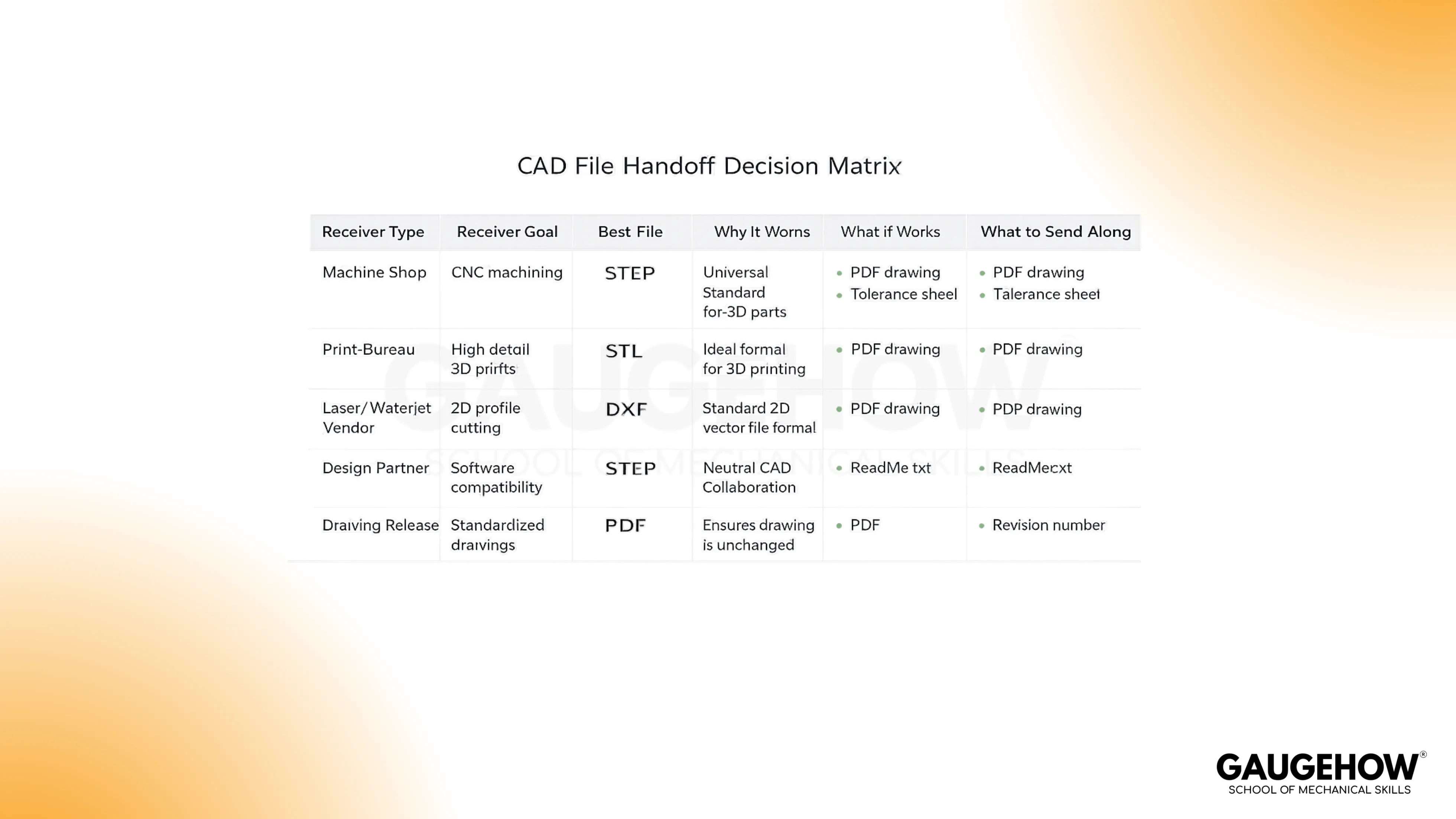
Pick the file for the receiver’s next job. Send STEP if the shop must measure, simulate, or program toolpaths. Send STL if the slicer must build layers. Send DXF for 2D profiles. Keep DWG for controlled drawing revisions inside one drafting stack across CAD file types.
Units mismatch scales the part, so the CAM paths land wrong. This is for you if you hand parts to shops, vendors, or print bureaus. You will choose the file, plus one add-on item, and move work forward.
Understanding CAD file types
Native CAD Files
Native files store the feature tree and constraints. This keeps changes are fast inside a CAD stack. Portability drops, so outside edits usually fail or drift.
Stores → enables → loses: feature history → controlled revisions → cross-tool reuse.
Neutral Exchange Files
Neutral exchange files store B-rep solids and surfaces. These imports support measurement, sectioning, and downstream setup. The feature tree is gone, so edits become face-based rebuilding.
Stores → enables → loses: solids/surfaces, assemblies, sometimes PMI → CAM, inspection, FEA setup → parametric intent.
3D Printing Files
Printing files store triangle meshes. The slicer consumes triangles, then generates layers and paths. Units can be ambiguous, so scale errors appear fast.
Stores → enables → loses: triangles with chord control → slicing and printing → true curves and design intent.
Other common formats show up in real handoffs: PDF for review, 3MF for printing, OBJ for visuals, and JT for lightweight viewing.
STEP for Manufacturing Handoff
STEP carries B-rep solids and surfaces as transferable geometry. CAM reads faces and edges without guessing curvature. Inspection tools measure features without rebuilding the model.
Assemblies often transfer cleanly. PMI may transfer, depending on the toolchain. Feature history does not transfer, so design edits shift to face operations.
A small habit prevents most rework. Export units explicitly, then verify one known dimension after import.
Send this when the receiver must measure, simulate, or program toolpaths.
Quick check: export units, then measure a known feature after import.
Micro example:
A shop asks for “model + drawing” before quoting. Send STEP for geometry, plus a one-page PDF with datums and tolerances. Quotes come back faster, and CAM matches intent.
STL for Printing Output
STL carries mesh triangles, not solids. Curves become facets, so surface quality depends on chord height and angle. Watertight meshes matter because open edges confuse slicing.
A mesh hides true radii, so inspection results drift across revisions. If a part will be machined later, a mesh export slows the workflow.
Send this when the receiver will slice layers and print parts.
Quick check: confirm watertight geometry, then set mesh for the smallest radius.
Difference between STEP and STL file: STEP vs STL
The decision behind STEP vs STL is simple. One format carries true geometry for downstream engineering work. The other carries printable facets for slicing and additive output.
Role | Benefits | System Requirements | Industry Use Case | Can Be Converted |
Product design engineer | Reusable geometry across CAD tools | CAD imports STEP reliably | Vendor collaboration, reuse | STEP → STL common |
CAM programmer/machine shop | Measurable faces for toolpaths | CAM reads solids/surfaces | Milling, turning, fixtures | STEP → STL common |
Metrology/inspection | Stable geometry for measurement | Viewer with measurement tools | CMM planning, reports | STEP → STL common |
FEA analyst | Clean geometry for meshing | FEA setup reads solids/surfaces | Structural, thermal setup | STEP → STL common |
Additive technician/print bureau | Slicer-ready model input | Slicer and mesh repair tools | Prototypes, additive builds | STL → STEP limited |
Procurement/quoting coordinator | Faster RFQ clarity | Viewer plus drawing workflow | RFQs and supplier quotes | STEP → STL common |
Geometry Detail
STEP keeps true curves and faces. STL approximates surfaces using triangles. Fine features suffer first when the mesh is coarse.
Editability
STEP supports face-based edits and rebuild features on imported geometry. STL edits are mesh repairs, not controlled dimension changes. Revision loops slow down fast.
Manufacturing Handoff
CAM and inspection rely on coherent faces and edges. STEP supports measurement, sectioning, and toolpath setup. STL blocks those steps unless someone reverse engineers geometry.
3D Printing Output
STL matches the slicer’s input model. STEP still needs meshing before slicing. Print quality follows mesh settings, not the file name.
DWG file for controlled drawings
DWG stores layers, blocks, linetypes, layouts, and annotation structure. This keeps drawing authoring efficient inside one drafting stack. Cross-tool translations can shift fonts, dims, and styles.
Xrefs matter in real work. Missing Xrefs break context, so reviewers see wrong geometry. Plot settings matter too, because scale errors sneak into releases.
Send this when drawings stay revision-controlled inside one drafting environment.
Quick Check: resolve Xrefs, then confirm plot scale matches the title block.
DXF file for Shop Exchange
DXF stores vectors for broad exchange. Layers, blocks, and linetypes usually travel well when exported cleanly. Shop tools often prefer simple entities over complex splines.
Open DXF contours break nesting, so the shop emails you at midnight. Duplicate lines create double cuts, so parts burn or chatter. These are export hygiene problems, not process problems.
Send this when the receiver needs 2D compatibility across mixed tools.
Quick check: closed contours, no duplicates, simple layer names.
Micro example:
A laser vendor rejects a profile for “open loops.” Small gaps and duplicates caused the failure. Close contours, delete overlaps, simplify splines to arcs, then resend. Cutting starts without further questions.
DWG vs. DXF: DWG vs DXF
DWG vs DXF splits into authoring versus sharing. DWG protects drafting structure inside controlled revisions. DXF prioritizes exchange across unknown receivers and shop software.
Primary Role | Coding Style | File Weight | Tool Freedom | Best-Fit Workflows |
Internal revision-controlled drawings | Binary | Often smaller | More restricted | In-house drafting control |
Vendor drawing exchange | ASCII | Often larger | Broad | External sharing |
Laser/waterjet profiles | ASCII | Often larger | Broad | Cutting profiles |
CNC router profiles | ASCII | Often larger | Broad | Routing and nesting |
Nesting/quoting portal upload | ASCII | Often larger | Broad | RFQ portals |
Archival + long-term accessibility | ASCII | Often larger | Broad | Long-term readability |
Vector Backbone
Both formats store vectors, not pixels. Geometry stays crisp at any zoom. Entities remain selectable, so edits remain possible.
File Weight and Transfer Friction
Binary storage packs data efficiently, so DWG often stays smaller. ASCII storage is verbose, so DXF often grows larger. Large DXFs slow uploads and imports on older shop systems.
Compatibility and Tool Freedom
DWG fits best when the receiver uses a known drafting ecosystem. DXF travels better across mixed software and lightweight shop tools. Translation friction drops when the receiver expects DXF.
2D vs 3D Expectations
Both formats can carry 3D entities, but most shops treat DXF as 2D. A 2D exchange file does not replace a 3D manufacturing handoff. Send solids when CAM needs solids.
Difference between DWG and DXF files
Accessibility by design
Use DWG as an authoring home, and DXF as an exchange bridge. This matches how drawings move through controlled releases. It also matches how shops consume profiles.
Binary vs ASCII reality
Binary encodes compactly, so storage and transfer often improve. ASCII spells data out, so translation and parsing often improve. Each choice has a cost, so pick the receiver toolchain.
Typical use-case split
Keep DWG internal while drawings still change and approvals run. Export DXF outward for shops, portals, and mixed CAD stacks. This keeps revisions controlled and exchange simple.
Understanding IGES basics
IGES basics show up in legacy surface workflows. IGES often carries surface-heavy geometry rather than robust solids. Stitching and trim failures are common after import.
When a receiver needs solids for CAM or inspection, STEP is usually safer. When a vendor requests IGES, send IGES and include a STEP fallback.
Send this when the receiver explicitly requests IGES for a surface workflow.
Quick check: Stitch surfaces after import, then confirm the solid forms.
Conclusion
Pick the file by the receiver’s next job, then prevent rework with one check. STEP supports measurement, CAM, and analysis setup. STL supports slicing and printing. DWG supports controlled drawing authoring, while DXF supports shop exchange. When you choose CAD file types this way, handoffs move forward without midnight emails.
FAQs
Which CAD file format should I send to a machine shop?
Send STEP plus a focused PDF drawing. The shop programs from geometry, then uses the PDF for intent. This reduces RFQ back-and-forth and prevents tolerance surprises.
Can you convert STL to STEP without losing accuracy?
Not reliably. A mesh has triangles, not true faces. Converting back rebuilds geometry, so small radii and edges degrade first.
Best file type for laser cutting: DXF or DWG?
DXF is usually safer for exchange. Many shop tools import DXF with fewer assumptions. Keep contours closed, delete duplicates, and use simple layer names.
Why does my STEP file import with wrong units?
Export and import defaults can disagree. One wrong unit scales every feature. Measure one known dimension immediately after import, before quoting starts.
CAD-CAM-CAE Work Platform
Find or Post CAD, CAM and CAE freelance projects, full-time jobs and Internships.
GaugeHow is the platform built for core engineering work. Whether you need a freelancer for a CAD project, a full-time hire, or an engineering intern,post it here and get matched with the right person.


