Scan-To-CAD Workflow: STL To STEP/IGES Complete Guide

A scan-to-CAD workflow is the reverse engineering chain that turns scanned mesh data (STL, OBJ, PLY) into editable CAD geometry you can measure, modify, and hand off.
The mesh is a reference shape, not design logic, so the deliverable is usually a rebuilt model exported as STEP or IGES for redesign, tooling, machining, or manufacturing.
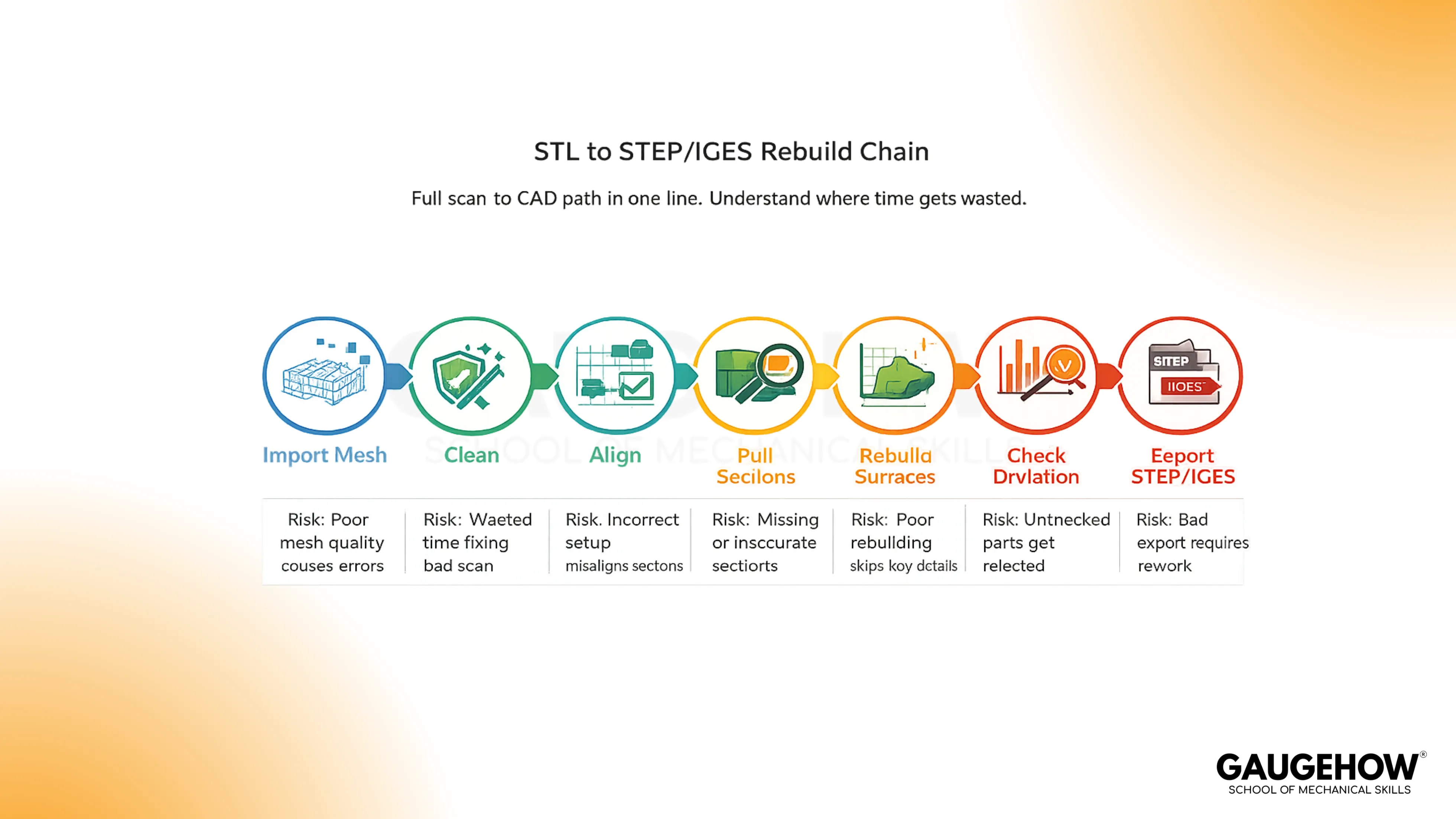
Scope: Mesh cleanup, alignment, sections and curves, surface rebuild, deviation checking, STEP or IGES export, plus the mistakes that waste hours.
Step | Benefit | Limitation | Example Use |
Import | Correct scale and reference | Unit mismatch creates a rebuild | Legacy part scanned to STL |
Clean | Stable sections and smoother fits | Over-smoothing can erase edges | Remove spikes and floor noise |
Align | Datums stay true across edits | Bad axes ruin symmetry features | Lock axis, plane, symmetry |
Section | Design intent becomes editable | Noisy curves create wavy surfaces | Profiles, silhouettes, feature lines |
Surface | Controlled geometry replaces triangles | Poor continuity causes patch seams | Planes, cylinders, blends, freeform |
Validate | Accuracy becomes defensible | Skipping this ship's hidden errors | Deviation map in critical zones |
Export | Neutral handoff works across CAD | No feature tree after translation | STEP for solids, IGES for surfaces |
You are usually here because the physical part exists, but the native CAD file does not. Maybe a bracket needs a fitment change, a housing needs a repair feature, or a supplier sent only a mesh.
The trap is treating the mesh like a CAD model, because triangles look real on screen, but they do not behave like engineering geometry when you start changing dimensions.
A clean workflow keeps you out of that trap. You use the scan as a reference, recover design intent with sections and curves, rebuild surfaces and solids that can actually be edited, and then you prove accuracy with deviation before you export anything.
That last proof step matters because shop and tooling teams will trust what you send, and rework starts when the model looks fine but is off where it counts.
What Scan To CAD Means
Scan-to-CAD is not “opening an STL in CAD.” It is the reconstruction of usable geometry from scan data, so the result can survive real edits, real tolerances, and real downstream tools.
The scan captures shape. The rebuild captures intent, meaning axes, symmetry, feature boundaries, and surfaces that behave predictably when you modify them.
The simplest way to think about it is the Mesh-To-Model Chain.
You start with reference triangles, then you rebuild curves and surfaces, then you close the body when the job needs a solid, and only then do you create a neutral deliverable for other teams.
Design Intent Inside A 3D Scan To CAD Rebuild
In a 3d scan to CAD rebuild, the scan is your measurement reference, but the CAD model becomes your engineering source of truth. That matters because design intent shows up as stable datums, controlled radii, repeatable hole patterns, and symmetry that you can edit without the model collapsing. When that intent is missing, each revision becomes manual patchwork.
Why You Still Rebuild To Convert STL To CAD Model
Many tools can “wrap” or “solidify” a mesh, and that can create a body you can save, but it often does not create geometry you can trust. A triangle mesh approximates the outside skin.
It does not store cylinders as cylinders, planes as planes, or fillets as controlled radii. So changes that should take minutes become sculpting.
When you try to convert STL to cad model without rebuilding, two problems usually show up. First, edges and faces are noisy, so mates, sketches, and offsets become unstable.
Second, manufacturing decisions get risky, because tiny mesh artifacts turn into toolpath chatter, bad sealing faces, or draft that is not actually consistent.
A rebuilt model does the opposite. It replaces triangle noise with surfaces and solids that reflect how the part was likely designed, which is why it edits, measures, and exports cleanly.
Inside The Scan To CAD Workflow
This is the chain that keeps the work defensible: you prepare the mesh, lock orientation, extract intent, rebuild geometry, prove deviation, and then export. Once you follow that order, the downstream handoff stops being a gamble.
Import The Scan
Start by importing the scan in the format you received, usually STL, OBJ, or PLY. Units are the first silent failure mode, because scanners and mesh files do not always carry trustworthy unit context.
A quick check on one known dimension saves you from rebuilding a part at the wrong scale.
Clean The Mesh
Remove anything that is not the part: floor fragments, fixtures, stray points, and noise around sharp edges. Cleanup matters because the mesh is your reference, and unstable reference data produces unstable sections.
If a face looks like sandpaper, your fitted geometry will chase that roughness unless you control it early.
Align The Part
Alignment is not cosmetic. Every later plane, section, and fitted cylinder depends on it. Establish the main axis, define symmetry if it exists, and lock a consistent orientation that matches how the part will be measured and manufactured.
Skipping this step is how you end up with crooked planes, “almost” round holes, and edits that drift when you mirror or pattern features.
Pull Sections
Sections and guide curves are where you recover design intent. Slice through functional regions, then trace profiles that represent the part’s logic, not the mesh’s triangles. Use silhouettes for outer boundaries, section curves for critical profiles, and feature lines for sharp transitions.
The goal is a clean scaffold that your surfaces can follow without guessing.
Build Surfaces
Use fitted surfaces where the part is clearly analytic, like planes, cylinders, cones, and controlled blends. Use freeform surfaces where the shape is genuinely organic or where tooling created subtle transitions.
Better sections lead to cleaner surfaces, and cleaner surfaces lead to a model that edits predictably instead of warping after small changes.
Close The Model
A surface model can be enough when the deliverable is an inspection comparison or reference geometry. Many mechanical jobs still need a closed solid, because solids behave better for downstream edits, CAM preparation, interference checks, and dimension control.
The decision is simple: If someone must modify, machine, or tolerate the model, a closed body usually reduces risk.
Check Deviation
Deviation checking is the moment you stop believing and start proving. Compare the rebuilt model back to the scan, then judge the result against the tolerance that actually matters for the part. Functional fits, sealing faces, and bearing seats need tighter control than cosmetic skins, so treat tolerance as region-specific, not one global number.
A practical gate helps: Pick three critical zones, measure max deviation there, and confirm the sign and direction make sense. If the model is outside tolerance, fix the scaffold or surfaces before you export, because bad exports do not get better downstream.
Export The CAD File
Export STEP when the receiver needs a solid or hybrid model for edits, CAM prep, or inspection. Export IGES when the handoff is surface-led, and the receiver prefers working from surface sets.
Include one short note with the file: Units, target tolerance, and which regions were held tight. Then open the export in the receiving CAD once and spot-check two datums and one critical fit before you send it.
STEP Vs IGES Vs STL
Feature | STEP | IGES | STL |
Data Type | Solid and surface geometry | Mostly surface geometry | Triangle mesh |
Best Fit | Cross-CAD mechanical handoff | Surface transfer workflows | Printing and visual reference |
Edit Behavior | Stable for measurement and edits | Depends on surface quality | Edits feel faceted and fragile |
Common Risk | Translation tolerances vary | Gaps and trims after import | False “precision” from triangles |
Typical Example | Send to another CAD team | Send surface set to rebuild | Send to printer or viewer |
Choosing Format: Export Step IGES From Scan
In practice, export step iges from scan only after the deviation result matches the tolerance that matters for the part.
STEP is the safer default for multi-team mechanical work.
IGES earns its keep when surfaces are the deliverable and the receiving workflow is built around surfacing.
Where Engineers Use It
Automotive And Motorsports
Scan-based rebuilds show up when brackets, housings, and mounts must be modified fast, but the OEM CAD is unavailable. The cause-and-effect is direct: mesh reference gives shape, but rebuilt CAD enables controlled changes and repeatable fixturing.
Aerospace And MRO
Repairs and replacements need traceable geometry. A deviation-checked rebuild reduces the risk of a part that looks right but fails fit, especially around interfaces and inspection datums.
Manufacturing And Tooling
Molds, dies, fixtures, and gauges need stable surfaces and solids. Mesh-only handoffs often create toolpath and inspection ambiguity, while rebuilt CAD lets teams section, draft, and dimension cleanly.
Industrial Maintenance And Spares
Legacy equipment rarely has clean CAD archives. A rebuild turns a one-off scan into a reusable part definition, which matters when spares must be remade again later.
Consumer Products And Plastics
Housings and snap features depend on controlled radii, parting logic, and draft. The rebuild step matters because triangle edges do not encode those manufacturing constraints.
Energy And Process Equipment
Pumps, valve bodies, flanges, and sealing faces punish sloppy geometry. Rebuilt CAD plus deviation proof protects sealing performance and alignment during assembly.
Mistakes That Cost Time
Unit Drift At Import
A scan that is off by 10× can still look believable, so the error survives until late. Confirm one known dimension immediately, because every later section and surface inherits the scale.
Verify: Measure one known feature (caliper value, drawing callout, or mating part) before any cleanup.
Aggressive Decimation In Critical Zones
Decimation helps performance, but it can flatten edges and blend transitions you actually need. Reduce density only where curvature is low, then protect sharp boundaries and fits.
Verify: Zoom on a sharp feature line (edge break, corner, hole rim) and confirm it still reads clean and continuous.
Alignment Without Datums
Freehand orientation creates a model that cannot be trusted when mirrored, patterned, or measured. Fit one main axis and one plane, then lock symmetry if it exists.
Verify: Check orthogonality: one axis and one plane should resolve as clean 90° references when you section.
Tracing Noisy Sections Instead Of Intent Curves
A curve that follows triangle noise produces rippled surfaces and unstable offsets. Smooth the reference first, then trace the engineering boundary, not the scan texture.
Verify: Pull the same section twice in nearby planes; the intent curves should stay consistent, not “wander.”
Surfacing Without Continuity Discipline
Patchwork surfaces might pass a visual check but fail downstream at blends and edges. Keep joins predictable and treat machined and sealing regions as continuity-critical zones.
Verify: Run a quick curvature or zebra check at joins where the part will seal, mate, or be cut.
Export Without A Receiving-System Open Test
Neutral files import differently across CAD systems, so a file can look fine on your side and break on theirs. Open once in the target CAD, then spot-check the interfaces that matter.
Verify: Confirm units, two datums, and one critical interface after import in the receiving system.
FAQ
Can a mesh be turned into CAD without rebuilding geometry?
Some tools can create a “solid” from triangles, but it rarely behaves like engineering CAD. Edits, offsets, and precision faces often fail because the shape is still faceted. Rebuilding surfaces and solids is the reliable path when tolerances matter.
What is the practical difference between STEP, IGES, and STL after scanning?
STL is triangles for reference or printing. STEP is a common neutral CAD handoff for inspection and modification across systems. IGES is an older exchange format that still appears in surface-heavy workflows. None of them restores native parametric history.
Why do sections and guide curves matter when rebuilding from a scan?
Sections turn raw scan shape into controlled geometry. They capture intent like symmetry, profiles, and feature boundaries. Without sections, surfaces chase triangle noise, so later edits drift, and the model becomes harder to validate and harder to manufacture.
How accurate should the rebuilt model be before you send it out?
Accuracy should match function. Control critical zones more tightly than cosmetic zones. Validate with a deviation map, then spot-check measured dimensions on key datums. If you cannot state a tolerance target per critical feature, the handoff stays risky.
Which file should you send for machining, tooling, or design edits?
STEP is usually the safest neutral handoff for mechanical collaboration because it imports widely. IGES can be useful for surface workflows when surface fidelity matters. If the recipient must edit or tolerate the part, avoid sending only an STL.
CAD-CAM-CAE Work Platform
Find or Post CAD, CAM and CAE freelance projects, full-time jobs and Internships.
GaugeHow is the platform built for core engineering work. Whether you need a freelancer for a CAD project, a full-time hire, or an engineering intern,post it here and get matched with the right person.


