CAD vs CAM vs CAE: Differences You’ll Never Mix Up

CAD creates geometry and release documentation, CAE proves that geometry under loads, and CAM turns geometry into cutter motion. Separate them by outputs: model and drawing, simulation results, and posted NC code with a setup sheet. Mix outputs, and late changes multiply rework.
Rule: Name the artifact, then verify the handoff.
Output Selector Table
Question You Need Answered | Tool | Output Artifact | Fast Verification Check | Who Owns It |
What is the exact shape and interface? | CAD | Model and drawing | Datums and mating faces match intent | Design engineer |
Will it survive the loads and constraints? | CAE | Mesh and results | Reactions balance the applied loads | CAE analyst |
How will the cutter remove material? | CAM | Toolpaths | No collisions and safe clearances | CNC programmer |
What file should a supplier receive? | CAD | STEP and drawing pack | Units and revision stamp match | Design engineer |
What should the inspection measure and where? | CAD | Drawing with GD&T | Datum scheme is measurable on the fixture | Quality engineer |
What will the machine actually run? | CAM | Posted NC code | Offsets and tool calls verified | CNC programmer |
In integrated CAD/CAM/CAE environments, artifact mismatches represent a common source of downstream errors. When incorrect file types are passed between stages — such as a 2D drawing being transferred to a CAM system that requires a 3D solid with defined stock allowance — the production process is disrupted.
Similarly, neutral file exports used in CAE workflows can result in contact pair failures, as face identifiers are not consistently preserved across translation formats. Manual modifications applied directly to NC code introduce revision discrepancies, causing the machining instructions to diverge from the master model.
These individual inconsistencies, while appearing minor in isolation, tend to accumulate across engineering change notices, contributing to increased rework and extended production timelines.
CAD CAM CAE difference: Outputs That Matter
Thinking about the CAD CAM CAE difference as output contracts keeps teams aligned. Each output has an owner, a risk, and a simple verification gate. Use the table to choose fast and avoid rework.
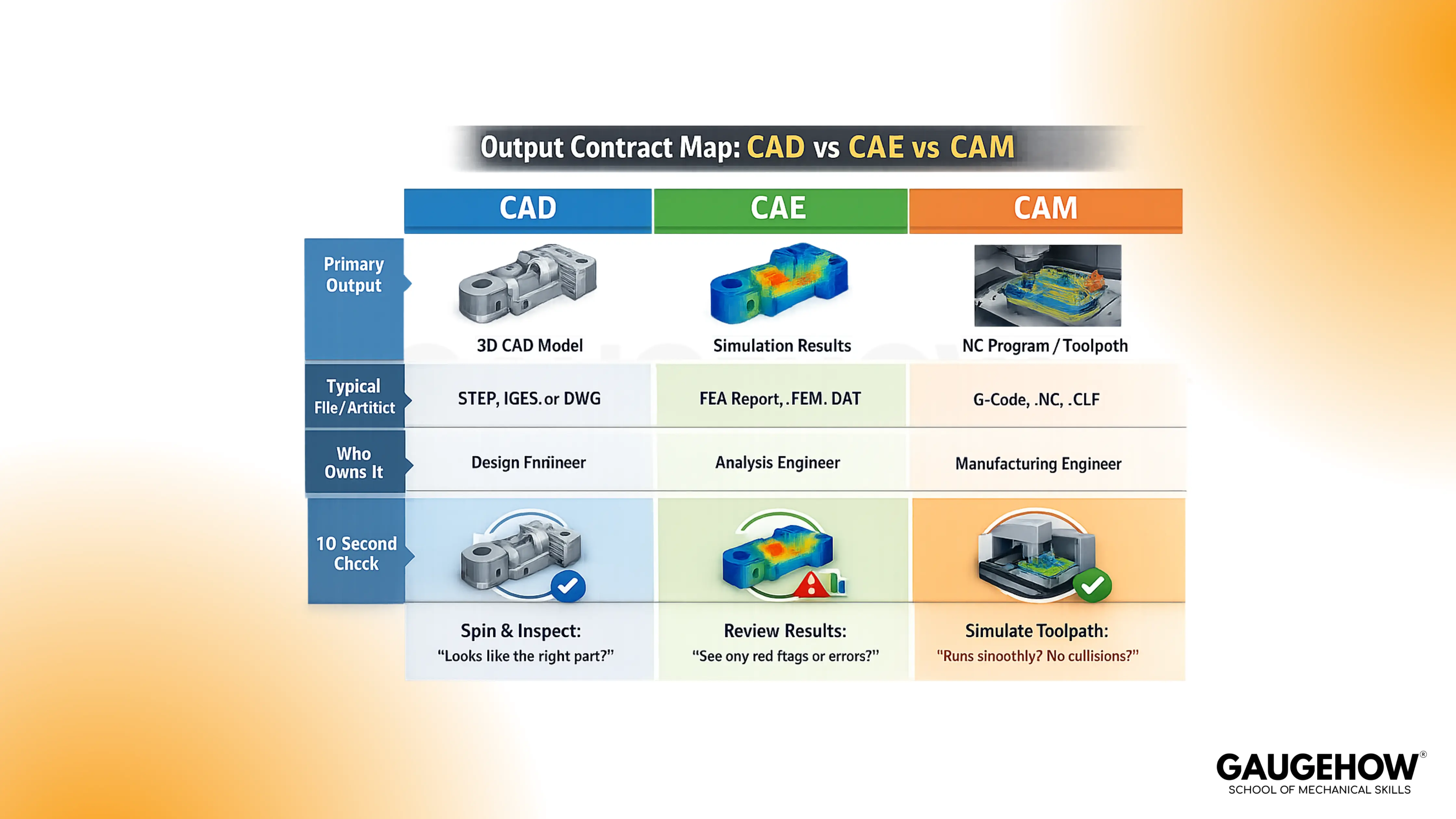
The Three Outputs
CAD outputs a parametric model, drawings, and a release package. Trouble starts when datum schemes are weak, so mates shift, and tolerance stacks drift. Confirm the datum scheme, the mating faces, and the revision stamp before handoff.
CAE outputs a mesh, boundary conditions, solver settings, and results. Bad setups happen when loads or contact pairs miss reality, even with perfect geometry. Check reaction balance, contact status, and mesh quality at critical features.
CAM outputs toolpaths, a setup sheet, and posted NC code through apost-processorr. Scrap happens when cutter engagement, clearances, or controller format is wrong. Verify collision-free simulation, work offsets, and tool lengths on the same revision.
Who Touches Which Output In Real Teams
Design engineers own the CAD model intent and drawings. CAE analysts own the simulation setup because boundary conditions dominate outcomes. CNC programmers own CAM toolpaths and the post processor, because controller rules are strict.
Manufacturing engineers protect the handoffs between outputs. Quality engineers validate datum callouts against fixturing and measurement access. Clear ownership keeps one revision defensible across design, build, and inspection.
CAD vs CAM: Where Geometry Turns Into Motion
What Leaves CAD, And What CAM Actually Needs
CAD produces geometry, but CAM needs manufacturing intent. A drawing carries tolerance intent, yet it does not carry tool intent. Solid export carries surfaces, but it can miss stock allowance and fixture reality.
Do one check every time: confirm units, define stock, then set the work coordinate system from the datum scheme.
Toolpath Is Not Intent
A toolpath is motion, not design intent. Tolerance stack belongs to function at interfaces, but stock allowance belongs to manufacturability, and cutter engagement belongs to cutting stability.
Mixing these creates drift, because a part can meet size yet fail fit, or it can fit yet chatter and gouge. Lock one check: keep tolerance intent in CAD and drawings, then define stock and engagement rules in CAM before posting.
Toolpath Regeneration
CAM outputs toolpaths, but toolpaths are not geometry. Motion is calculated from surfaces, tools, and cutting rules, so it can stay valid-looking while becoming wrong.
After a change, running an old path is the fastest route to scrap. Treat these regen triggers as your default release gate.
Changing a fillet radius can leave uncut stock.
Moving a hole axis can hit a clamp.
Editing a pocket depth changes stepdowns and load.
Swapping a mating face can shift work offsets.
Updating stock allowance changes cutter engagement.
Reordering operations can change heat and chatter.
Switching tool diameter forces new clearances.
Regenerate toolpaths after any trigger, then replay the simulation to the end. Record the change link in the setup sheet. That habit prevents silent drift between model and motion.
Post Processor For CNC Controller
CAM builds a generic toolpath plan, then the post-processor creates controller-specific NC code. Problems start when a post outputs unsupported cycles or unsafe retracts
Hand edits inside the NC code create a second truth nobody tracks. Keep one gate: compare posted header, offsets, and tool calls to the setup sheet on every revision.
CAM Verification That Shops Trust
Simulation output only matters when it matches the real setup. Collisions hide when fixtures, clamps, and tool stickout are missing.
Run collision checks, confirm fixture clearance, then sanity check the setup sheet against the same revision stamp. Accept only when the simulation shows no collisions, no gouges, and correct work offsets.
CAD vs CAE: When Shape Becomes Proof
Model vs Mesh In CAE
CAD outputs clean surfaces, but CAE outputs a discretized mesh. Errors appear when sharp gradients sit on coarse elements near fillets and holes.
Different meshes can change results even with identical geometry. Review mesh quality at load paths and contact zones before trusting plots.
Boundary Conditions And Contact Pairs
CAE produces numbers, but setup choices create those numbers. Over-stiff constraints can hide bending, while loose contact pairs can invent separation. Imagine a bracket bolted with four M10 bolts, loaded by 2 kN.
Fixing the full base face looks stable, but it removes bolt compliance and shifts peaks. Constrain bolt regions, check contact status, then verify reaction paths.
Reading Results Like An Engineer
Results output includes stress, displacement, and margin to allowable. False confidence shows up when reactions do not balance, or convergence never stabilizes.
Read three things every run: margin, reaction balance, and convergence trend. Trust a result only when reactions match loads closely, and peaks stabilize with refinement.
The CAD To CAE To CAM Chain
The Hand-Off Points Where Data Gets Lost
Each handoff changes format and meaning. Neutral export drops feature history, and face identity can change on import.
Units and coordinate systems can also flip quietly, so fixtures and boundary conditions shift. Reimport the export into a clean session, then verify datums, axes, and units.
What Must Be Rebuilt After A Change
1. CAD needs a feature rebuild, drawing regen, and updated revision stamps.
2. CAE needs a remesh plus refreshed boundary conditions and contact pairs.
3. CAM needs regenerated toolpaths, reposted NC code, and an updated setup sheet.
Skipping any rebuild creates two versions that both look current.
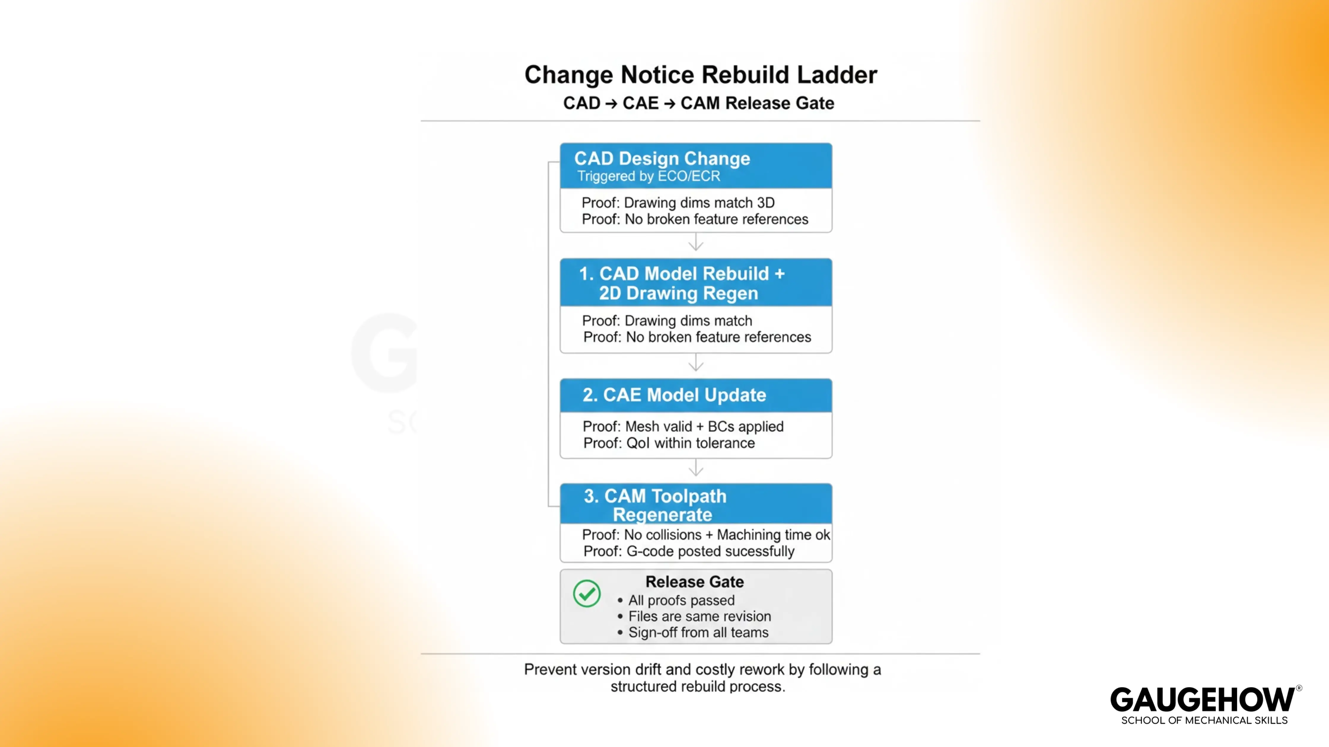
A Micro Example That Pays Off
The plate thickness changes from 8 mm to 10 mm. CAD updates, but a datum reference moves with the face. CAE keeps an old contact pair, so reactions look plausible but wrong.
Meanwhile, CAM runs the previous pocket path and leaves 0.4 mm uncut stock. Gate release by reimporting the STEP, remeshing, and rerunningthe toolpath simulation, then accept only when the remaining stock stays within 0.1 mm.
CAD CAM CAE Tools In Practice
Integrated Suites vs Best Of Breed Stacks
Integrated suites reduce friction because one data model feeds outputs. Blind spots still appear when teams assume integration removes verification.
Best of breed stacks can be stronger in one discipline, but translations add drift points. Pick the stack that matches your revision rate and tolerance risk.
What To Choose By Job Role
Students should start with modeling and drawings, because geometric habits compound. Design engineers need datum discipline and release packages before anything else.
CAE analysts should build judgment in meshing and boundary conditions. CAM programmers should focus on setup thinking, cutter engagement, and post control.
Learning Path
Learn CAD First, But Learn CAM Earlier Than You Think
CAD unlocks everything because every downstream tool consumes geometry. Rework starts when designers ignore fixtures, stock allowance, and cutter access.
Learn basic machining constraints while modeling, along with work offsets tied to datums. That single shift makes release packages buildable.
Add CAE When You Can Define Loads And Constraints
CAE pays off once you can describe load paths clearly. Button pushing creates pretty plots, but weak assumptions create bad decisions.
Start with simple constraints, then add contact pairs only when needed. Build the habit of checking reactions, convergence, and margins every run.
FAQs
Does CAD generate G code?
CAD does not generate G code. CAD outputs geometry and drawings, then CAM uses that geometry to generate toolpaths and post-NC code through a post-processor.
What does CAM output?
CAM outputs toolpaths, a setup sheet, and posted NC code for a specific controller. Verify post settings and offsets, because wrong formatting can scrap parts fast.
Is CAE only FEA?
CAE is not only FEA. CAE includes FEA, CFD, and thermal or motion analysis, as long as the output is simulated behavior under defined loads and constraints.
What is the difference between CAD, CAM, and CAE?
CAD defines shape and documentation, CAE proves performance, and CAM plans manufacturing motion. Separate them by output artifacts, then run a quick verification before handoff.
Which should I learn first?
Learn CAD first, then add CAM basics early, because design decisions affect machining. Add CAE after you can define loads, supports, and acceptance criteria.
Conclusion
Most confusion disappears when you treat CAD, CAE, and CAM as output contracts. Name the artifact, then run the gate: datums and revision stamp for release, reaction balance for analysis, and collision-free simulation plus posted code for machining. When a change notice hits, rebuild the chain in that order and release one revision with confidence. To practice this end-to-end, train on GaugeHow’s CAD workflow projects.
CAD-CAM-CAE Work Platform
Find or Post CAD, CAM and CAE freelance projects, full-time jobs and Internships.
GaugeHow is the platform built for core engineering work. Whether you need a freelancer for a CAD project, a full-time hire, or an engineering intern,post it here and get matched with the right person.


