History of CAD: From Sketchpad to Cloud CAD in 60 Years

In the history of CAD, every decade removed one constraint that slowed real engineering work. Drafting moved from redraw-heavy drawings to editable 3D solids, then parametric change control made revisions cheaper, and cloud workflows reduced “which file is right” chaos. Use this page as a CAD timeline plus the practical checks that keep models, drawings, and exports aligned.
CAD Timeline
Sixty years of CAD is easier to understand as a sequence of bottlenecks getting removed. First came editable geometry, then unambiguous 3D, then predictable change, and finally shared revision truth across teams.
Scan the eras in order, and you will see exactly what became possible at each step, along with the failure it pushed out of the workflow.
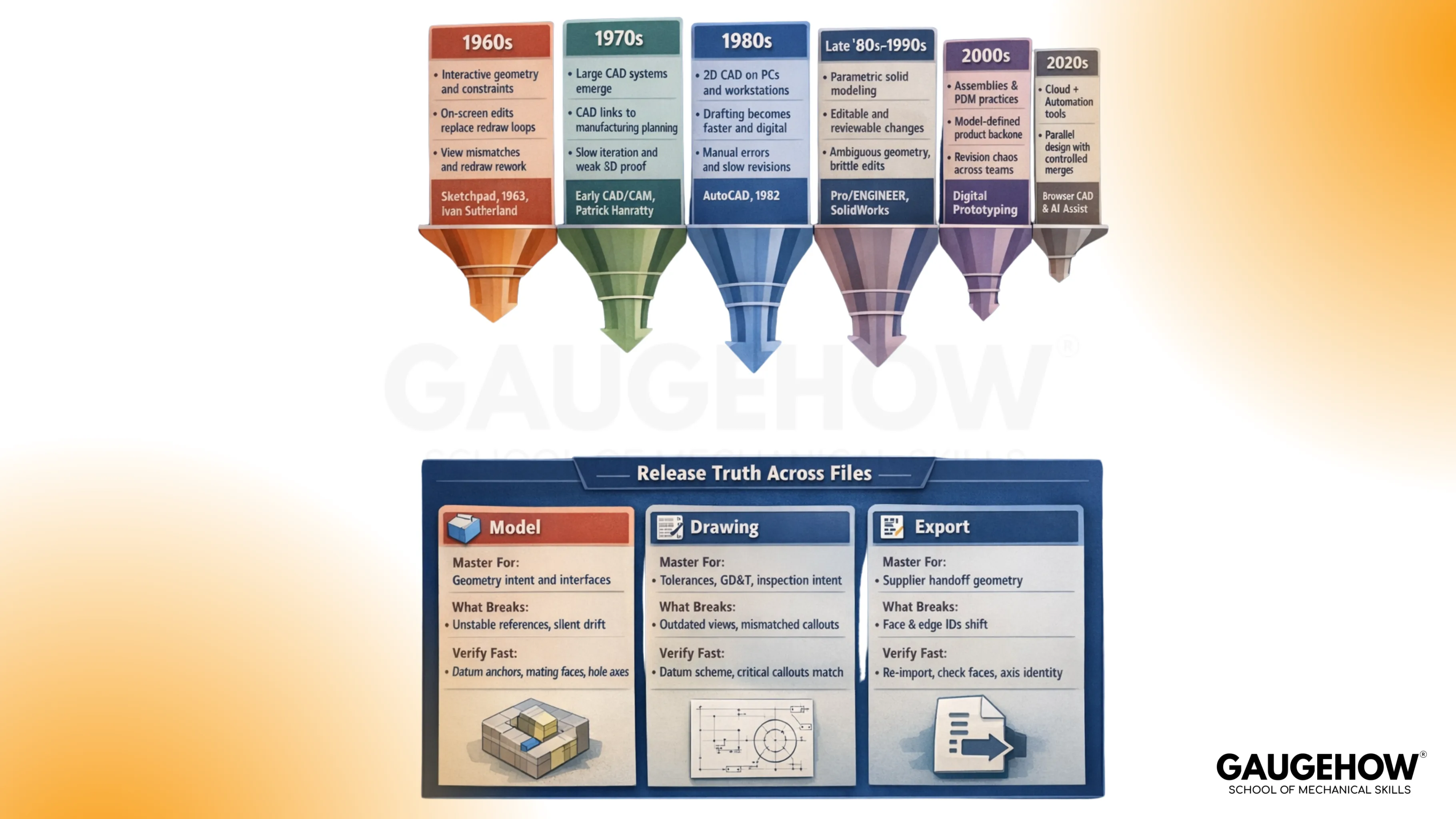
Era | What Changed Technically | What Changed In Workflow | What Failure Did It Reduce | Anchor Milestone |
1960s | interactive geometry and constraints | edits happen on-screen, not by redraw | redraw loops and view mismatches | Sketchpad 1963, Ivan Sutherland |
1970s | compute and graphics push large CAD systems | EarlyCAD begins touching manufacturing planning | slow iteration and weak 3D proof | Patrick Hanratty, early CAD/CAM |
1980s | 2D CAD scales through PCs and workstations | Drafting throughput rises across the industry | manual drafting errors and slow revisioning | AutoCAD 1982, 2D adoption wave |
late 1980s–1990s | parametric features plus solid kernels mature | change becomes editable and reviewable | ambiguous geometry and brittle edits | Pro/ENGINEER 1987, SolidWorks 1995 |
2000s | assemblies, configurations, and release discipline | The model becomes the product definition backbone | revision chaos across teams | PDM habits, digital prototyping |
2010s | connected collaboration and better exchange | Review cycles shorten, and sharing becomes normal | duplicated files and stale handoffs | Onshape 2012, cloud workflows |
2020s | cloud-first plus automation support | parallel design and controlled merges improve speed | Which file is right?” fights | browser CAD maturity, AI assists |
Treat this CAD timeline like a map of bottlenecks. Each later section explains the mechanics behind one or two rows, so the evolution stays understandable rather than encyclopedic.
Pioneers Who Set The Rules
Eras changed, tools changed, and hardware got faster, but the real progress came from a few people pushing one stubborn idea at a time. One made geometry editable instead of redraw-only.
Another pushed design data toward the shop floor instead of leaving it trapped in drawings. A third made a change in behavior, so revisions could be controlled rather than patched. That is why these pioneers still show up in how you model, how you release, and how you prevent drift.
Ivan Sutherland
Introduced interactive graphics with constraint thinking through Sketchpad.
Solved redraw-heavy drafting by letting geometry behave consistently under edits. Created the modern habit of anchoring intent in relationships, not appearance.
Patrick Hanratty
Introduced early foundations that pushed CAD data toward manufacturing use. Solved the gap where design lived in drawings, but process lived elsewhere. Created the modern habit of expecting downstream toolpaths and setups to trace back to defined geometry.
Samuel Geisberg
Introduced practical parametric, feature-based modeling for engineering change. Solved brittle edits that forced partial rebuilds and re-drafting in complex parts. Created the modern habit of building stable references, then verifying interfaces after functional change.
Evolution Of CAD Modeling
The evolution of CAD becomes obvious when one part is carried through each modeling style. Use a simple bracket with a hole pattern and two mating faces. That part will expose what each era can prove and what it cannot.
Start with a wireframe.
Edges look correct until visibility and overlap create ambiguity. Hidden lines and intersecting ribs force interpretation, so two engineers can “see” two different parts from the same wireframe.
That ambiguity turns into wrong clearances and wrong inspection assumptions. Wireframe still helps for early layout, but wireframe modeling in CAD collapses once you need trusted contact and volume checks. Keep wireframe modeling in CAD for quick spatial planning, not for release truth.
Move to surfaces
Shape becomes controllable, especially on curved housings and panels. Surfaces can still fail in a way engineers recognize: non-watertight geometry. Gaps, trims, and continuity breaks can look fine on screen while behaving badly in downstream export or thickening operations.
Mechanical work needs shape and validity at the same time, so surfaces are powerful but discipline-heavy.
Shift to solids
Volume becomes unambiguous. Interference becomes real, not a debate. Assembly contact, clearance, and mass properties can be checked with repeatable outcomes.
Solid modeling turns “looks right” into “behaves right,” which is why it changed industry habits.
Add parametrics
Change becomes cheap because features carry relationships. A thickness update can propagate through ribs, fillets, and hole edge distances without re-drawing. Parametrics still require verification because fast updates can break interfaces silently.
A bracket that rebuilds cleanly can still violate a clearance stack or shift a locating axis, so interface checks remain the honest gate.
Solids, Parametrics, And The Real Meaning Of Change Control
Solid geometry made parts reliable. Parametric modeling made revisions controllable. Both together turned CAD into a system that can support engineering judgment rather than just drafting speed.
Focus on one mechanical consequence: interface drift. A change touches the thickness or a mating face, then the hole edge distance shifts, and then the assembly’s locating scheme becomes inconsistent. A rebuild success does not prove functional success. Proof comes from checking the same interfaces every time.
Run a short routine after any change that touches fit or function. Keep it repeatable across projects.
Rebuild the model, then re-check primary datums, hole axes, and mating faces that define location.
Validate one clearance and one interference in the loaded assembly condition.
Confirm drawing annotations still represent the same datum scheme and functional faces.
Release Truth Across Files
Design teams rarely lose time on modeling skills. Teams lose time on file truth. Model, drawing, and export can each look “right” while still being wrong in different ways.
Master Definition
Artifact | Master For What | What Commonly Breaks | What To Verify Fast |
Model | geometry intent and interfaces | unstable references and silent interface drift | datum anchors, mating faces, hole axes |
Drawing | tolerances, GD&T, inspection intent | outdated views and mismatched callouts | datum scheme and critical callouts vs revision |
Export | supplier handoff geometry | face and edge IDs shift after translation | Re-import face selection and axis identity |
A failure that engineers recognize shows up during inspection planning. Face and edge IDs shift after export, then CMM points land on a different surface than intended.
The part can fail inspection even when the design intent never changed. The argument becomes “which file was master,” when the real problem was missing verification after translation.
Neutral exchange is unavoidable, so treat it as transport. Formats like IGES and STEP file formats move geometry, but they do not guarantee stable feature intent, mate logic, or consistent face identity. Use IGES and STEP file formats when you must, then prove that critical selections survive re-import.
Keep the control routine boring. Boring routines prevent expensive surprises.
Import the export into a clean session, then confirm units and orientation.
Re-check the same functional interfaces used for release, starting with mating faces and locating axes.
Select one inspection-driven surface again, ensuring the same face gets picked after translation.
Cloud CAD And Collaboration
Cloud-based CAD reduced a different failure than earlier eras. Earlier tools improved modeling and editability. Cloud tools improved shared truth.
File-based workflows often create parallel realities. Two good engineers can make two valid changes on two copies, then ship two different exports. Assembly failure comes later, and the team wastes time proving which file was released.
Cloud workflows reduce that chaos by keeping one versioned source, a visible history, and reviewable changes. Branching supports exploration without polluting the release line. Merge discipline supports parallel work without silent overwrites.
Cloud tools still need a release mindset. Cloud-based CAD collaboration keeps people aligned, yet downstream exports can still translate face identity in unexpected ways. Lean on cloud-based CAD collaboration to reduce duplication, then keep the export verification routine as the final gate.
That arc closes the history of CAD in practical terms. Geometry became editable, then change became controlled, and now truth became shared.
Future Of CAD
AI will matter most where repetitive feature work eats hours. Patterning, hole series, rib networks, draft suggestions, and cleanup tasks will get faster. Engineering value comes from using that time to focus on interfaces, tolerance intent, and validation, not from letting automation guess the design.
Real-time simulation loops will shift rejection earlier. Bad load paths and weak sections get flagged while geometry is still flexible. Earlier feedback cuts late rework because stiffness and clearance fixes are cheaper before drawings and CAM lock-in.
AR and VR review will win on envelope validation. Service access, swing arcs, assembly sequence, and packaging checks become easier when everyone sees the same spatial truth at the same time.
Engineering judgment remains non-negotiable. Intent is a decision, not a feature. Someone still chooses what must not move, and what acceptance proof closes the loop.
Conclusion
CAD kept evolving for one reason: change had to become safer. Constraints reduced redraw pain, solids removed ambiguity, parametrics made revisions cheaper, and cloud tools tightened revision truth across teams.
The winning habit stays simple: protect functional interfaces, then prove exports before anyone cuts metal. Do that consistently, and the tools stop being “software” and start behaving like a controlled engineering system. Have a look at Gaugehow's CAD course details to develop industry-ready skills in this domain.
FAQs
1) What is the biggest turning point in the history of CAD?
Parametric solid modeling. It made change predictable because relationships carried intent,t and updates could be verified systematically.
2) Why did wireframes fade as a release method?
Ambiguity. Hidden edges and overlapping geometry force interpretation, and interpretation creates avoidable errors in downstream checks.
3) Why do surfaces still cause problems in mechanical workflows?
Non-watertight geometry. Trims, gaps, and continuity breaks can look fine while failing thickening, meshing, or export reliability.
4) Do IGES and STEP file formats preserve full CAD intent?
They preserve geometry well, yet they can lose feature history and face identity. Re-import verification is a reliable control.
5) What did cloud CAD actually fix?
Shared truth. Cloud workflows reduce duplicated files, improve version visibility, and shorten review loops, while still requiring disciplined release gates.
CAD-CAM-CAE Work Platform
Find or Post CAD, CAM and CAE freelance projects, full-time jobs and Internships.
GaugeHow is the platform built for core engineering work. Whether you need a freelancer for a CAD project, a full-time hire, or an engineering intern,post it here and get matched with the right person.


