2D Vs 3D CAD Software: Stop Guessing, Choose Right

2D CAD vs 3D CAD is a deliverable decision, not a skill badge. Use 2D when drawings drive fabrication, schematics, or layouts. Use 3D when fit, interference, motion, or change control matters. When both outputs are required, run a hybrid workflow and release the package as one.
Decision Flow And 90-Second Table
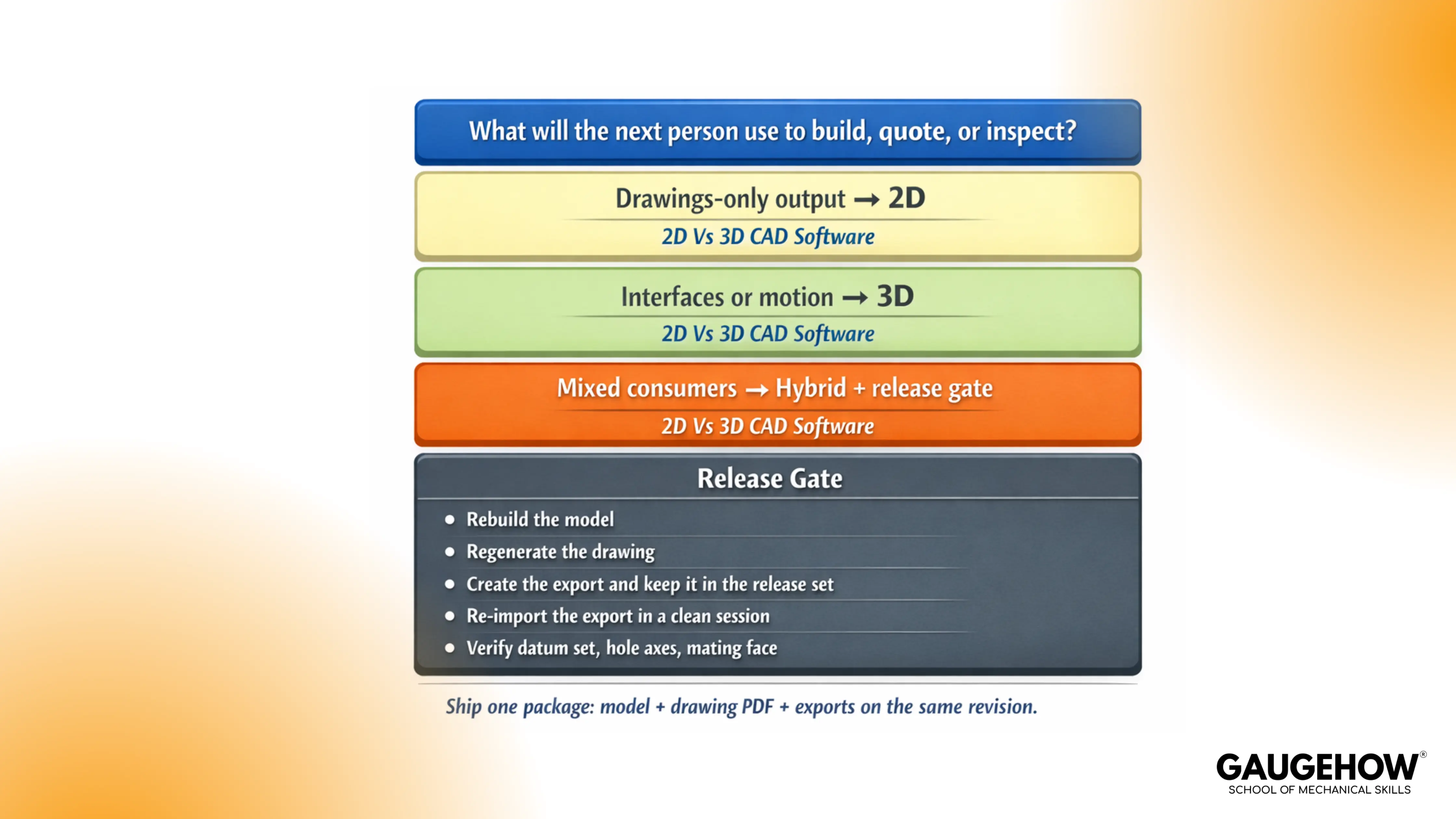
A clean choice starts with one question: what will the next person use to build, quote, or inspect? Once that is clear, most confusion disappears.
Decision In 90 Seconds
Your Situation In The Job | Choose | Why It Wins | Output You Must Ship |
Drawings are the contract for building or inspection | 2D first | fastest edits, clearest documentation | DWG/DXF plus controlled annotation |
Fit and clearance must be proven before building | 3D first | Interference and assemblies reduce rework | model + key interface sections |
Supplier quoting depends on profiles and dimensions | 2D plus export check | reduces interpretation on the shop floor | drawing pack plus clean DXF |
Revisions are frequent, and variants exist | 3D (parametric) | controlled changes propagate predictably | model with stable references |
Imported supplier geometry needs edits | 3D (direct) | edits without rebuilding history | repaired solids plus verified interfaces |
Curvature and stylingdominates geometry | 3D (surface or freeform) | continuity control beats patchwork solids | surfaced master plus manufacturable solids |
Different teams consume different outputs | hybrid | keeps model and drawing aligned | model, drawing PDF, and exporting the same revision |
2D CAD vs 3D CAD In Workflow Terms
Debate fades once you tie the choice to how work fails under change. Documentation-driven work breaks differently from fit-driven work.
2D CAD Drafting
2D drafting wins when the drawing is the product. Layouts, schematics, fabrication drawings, and legacy documentation refresh cycles live here because edits stay quick and the output scans well in production.
Ambiguity becomes the main risk. A view that forces interpretation turns into clarification loops, and those loops show up as delayed quotes and inconsistent inspection.
3D CAD Modeling
3D modeling pays back when geometry must survive revision load. Assemblies expose interference early, and envelopes stop being guesswork. Change control improves because intent can live in constraints and datums instead of living in people’s memories.
A fragile structure is the usual trap. Convenient face references drift after a thickness shift or a feature reorder, then exports re-identify faces, and downstream teams “measure the wrong truth.”
CAD Software Categories
Tool choice gets faster when CAD software categories are clear. Each category exists because mechanical teams need different kinds of control.
What Are The Different Types Of CAD Software?
Most workflows land in a small set of types of CAD software. Picking the right one is less about features and more about what must remain stable through edits, exports, and reviews.
Parametric CAD
Parametric systems protect intent through constraints and relationships. A healthy model changes predictably when a driving dimension moves, and critical interfaces keep their meaning.
One quick test reveals quality. Change a driving dimension, rebuild once, then verify the same interface surfaces and hole axes stayed logically anchored.
Direct Modeling CAD
Direct modeling helps when geometry arrives without a clean history. Imported supplier parts, legacy STEP files, and late-stage modifications often require fast edits without rebuilding a fragile feature tree.
Control improves when interfaces are locked first. Edits should happen around those anchors, not through them.
Solid Modeling CAD
Solid modeling covers most mechanical parts because mass properties, sections, and interference checks become straightforward when geometry is watertight.
Sectioning a key interface usually tells the truth faster than any visual spin. Wall thickness, clearance zones, and datum-driven features either exist or they do not.
Surface And Freeform CAD
Surface tools exist for curvature control and continuity. Freeform tools exist for organic shaping and concept refinement. Both can be essential, but both can also create messy trims and sliver faces that fail at export time.
Downstream reality matters here. If the export breaks, the workflow breaks.
Cost, Learning Curve, And What Slows Teams Down
A selection that looks “cheap” can still be expensive once revisions hit. The visible costs are licensing and hardware. The hidden costs are confusion, drift, and nonproductive file handling.
2D Cost And Skill Reality
2D tools are often cheaper to adopt and faster to train for basic drafting. Productivity stays high when standards are tight, and the drawing set stays simple.
Complexity increases training demand quickly. Layer discipline, annotation rules, and dimension schemes decide whether drawings scale across a team or collapse into personal styles.
3D Cost And Skill Reality
3D tools demand more training because the workflow is not just drawing. Modeling requires intent: datums, constraints, and predictable rebuild behavior. Hardware requirements rise with large assemblies and heavy drawings.
Payback arrives when fit and change control matter. Fewer physical surprisebeats faster sketching on most mechanical programs.
The Hidden Cost That Bites Teams
Tech-Clarity reported that engineers spend about 19% of their time, roughly a day a week, on non-value-added CAD data management tasks around CAD work. That waste grows when file discipline is weak, not when CAD is used.
Release the Gate That Stops Drift
Drift is rarely a CAD tool issue. Drift is what happens when a change touches fit or function, then the model, drawing, and export stop moving together. One person updates the thickness, another prints an older PDF, and a supplier imports geometry that re-identifies faces. That is how you end up with two “correct” files and one failed build.
A micro-example that feels familiar in real jobs:
Object: a hole pattern located from a datum scheme and one mating face.
Change: plate thickness shifts after review, so a face reference gets swapped because it is faster.
Shop-floor miss: fixture pins seat on a different face, so the part sits offset and the assembly binds.
Inspection miss: the CMM probes the wrong surface because the export changes face identity.
Paper miss: the drawing still looks fine, but the neutral file now carries a different intent.
That chain ends when release becomes a short, repeatable gate, not a last-minute export.
The sequence that stops drift under pressure:
Rebuild the model and confirm no critical features fail or are suppressed.
Regenerate the drawing and confirm that datums and callouts still reflect the revision intent.
Create the export and keep it inside the release set, not as a separate “quick send.”
Re-import the export in a clean session and confirm the geometry did not shift.
Check three interfaces every time: the datum set, the hole axes, and the mating face that seats the assembly.
Once the gate exists, lock the few outputs that must never drift. Everything else can change. These cannot.
The items that must remain identical across native, drawing PDF, and exports:
Revision stamp and naming that make the current set unambiguous.
Datum scheme used to locate critical features.
Hole axes that control fit and fastener alignment.
Mating faces that define seating and stack-up.
Clearance zones that prevent rubbing and binding.
Inspection-critical dimensions and notes that drive pass or fail.
When those items stay aligned, and the export gets reopened and checked like a supplier would, drift stops being a recurring argument and becomes a controlled event.
Release Package
Deliverable | Downstream Team Uses It For | Typical Format | One Verification That Catches Trouble |
Native CAD | design intent, updates, internal change control | native part and assembly | Rebuild clean, no failed features |
Drawing PDF | inspection, purchasing, supplier communication | Verify datums, notes, and revision stamp | |
Neutral Solid Export | supplier CAM, quoting, cross-CAD sharing | STEP or IGES | Re-import and re-check three interfaces |
2D Exchange | laser, plasma, legacy shop workflows | DWG or DXF | open in a viewer and confirm units and layers |
Mesh Export | print checks or visual mockups | STL (only when needed) | Confirm scale and orientation before sharing |
A short routine holds everything together. Rebuild. Regenerate. Export. Re-import. Verify the same three interfaces. Release one package.
FAQs
Is 2D CAD still used?
Yes. Drawings still drive fabrication, inspection, and supplier communication in many shops, especially where documentation is the contract.
Is 3D CAD better than 2D?
Not universally. 3D is better when fit, motion, and change control must be proven. 2D is better when documentation speed and clarity are the main output.
When should I use 2D vs 3D CAD?
Use 2D when the drawing set is the deliverable. Use 3D when geometry must survive edits and assemblies must be verified before build. Choose a hybrid when different teams consume different outputs.
Can 3D CAD replace drawings?
Sometimes, but not reliably across supply chains. Many inspection plans, compliance needs, and purchasing workflows still require drawing packs.
What is parametric vs direct modeling?
Parametric modeling protects design intent through constraints and relationships. Direct modeling edits geometry quickly, especially on imported files, without relying on a feature history tree.
CAD-CAM-CAE Work Platform
Find or Post CAD, CAM and CAE freelance projects, full-time jobs and Internships.
GaugeHow is the platform built for core engineering work. Whether you need a freelancer for a CAD project, a full-time hire, or an engineering intern,post it here and get matched with the right person.


