BIM vs CAD: Drawings Vs Building Models, Finally Clear

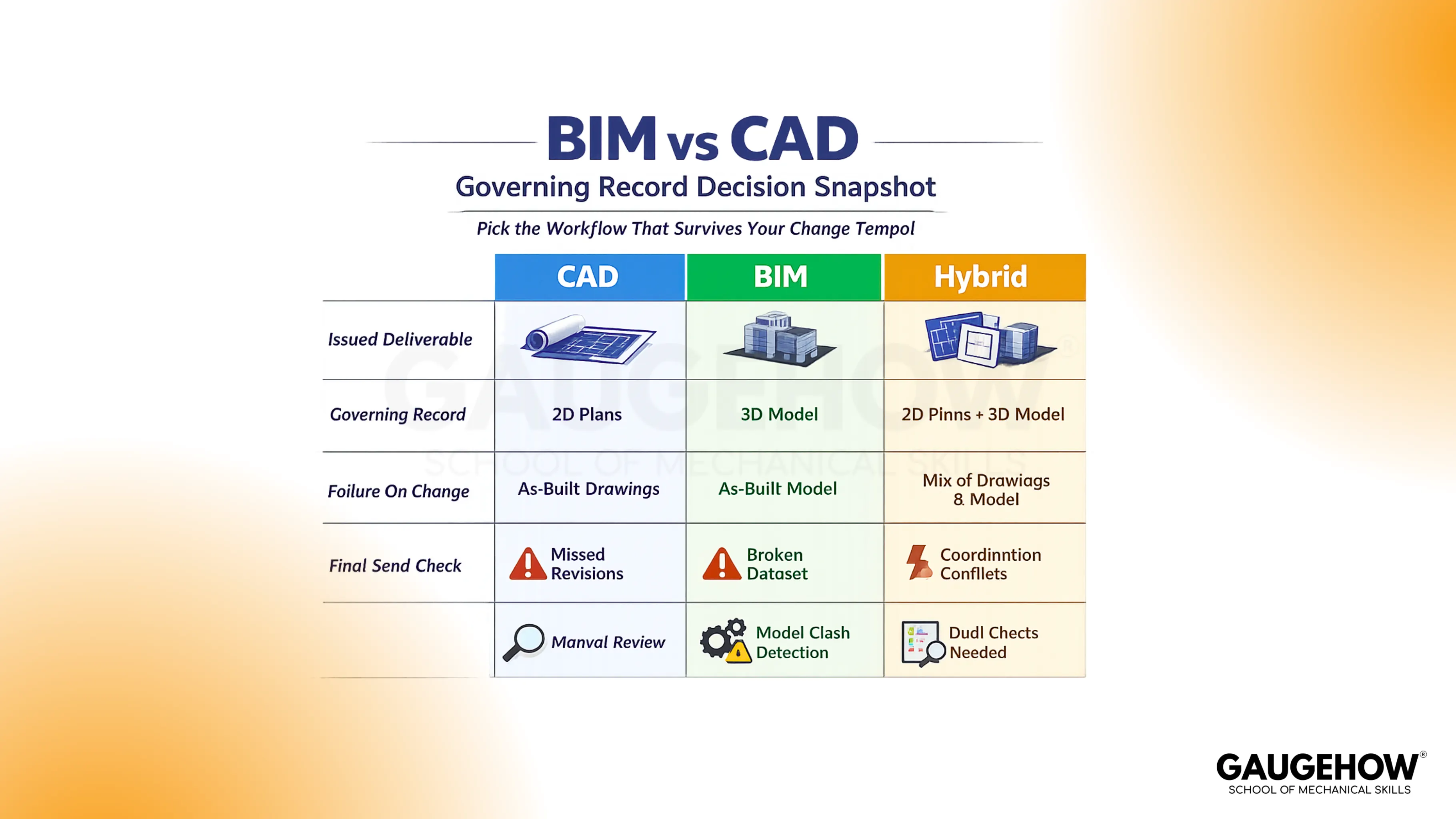
CAD helps you create drawings and models, then issue sheets that people build from. BIM helps you run one coordinated building database that generates drawings, schedules, and quantities. The BIM vs CAD difference that matters on real projects is where the governing record lives, and how reliably revisions propagate without creating two plausible answers.
A lot of confusion comes from using “BIM” and “CAD” as if they were competing software categories. They are really two different ways of controlling deliverables. One is sheet-governed, where correctness is proven by documentation discipline.
The other is model-governed, where correctness is proven by controlled regeneration and validation. Once you see that, you stop arguing about tools and start choosing the workflow that keeps up with your project’s changing tempo.
What Is CAD?
CAD stands for (Computer-Aided Design). In building work, it usually means drafting geometry to produce plans, sections, elevations, and details with tight dimensional control. CAD is at its best when the issued sheet set is the contract, and the team runs release discipline like a quality system.
Key characteristics of CAD deliverables include:
Explicit drawings, explicit responsibility. Each view shows what you put there, so completeness depends on your cross-checks across sheets.
Sheet-first control. The revision stamp and the issued PDF set become the governing record, so version control is not optional.
Fast detailing. Focused technical work stays efficient because you can drive clarity without building full relationships in every object.
Practical handoff formats. DWG and DXF exchange geometry well, while PDFs preserve issued intent cleanly.
Coordination relies on discipline. Conflicts are caught by overlay, review, and consistent checking, not by automatic relationship logic.
What Is BIM?
BIM is Building Information Modeling. In practice, it is a workflow where elements carry identity and data, not only geometry. Drawings and schedules are derived views of that coordinated model, so a change is meant to propagate through dependent outputs in a controlled way.
Key characteristics of BIM workflows include:
Objects carry meaning. A duct, beam, or equipment item has parameters that can drive tags, schedules, and view behavior.
One coordinated source. Teams coordinate around a shared model rather than passing separate drawings as separate truths.
Schedules are tied to elements. Quantities and equipment lists can be pulled from parameters, which reduces manual recounting when standards are clean.
Clash checking becomes routine. Interference surfaces earlier because systems exist in one coordinated environment.
Governance matters more than geometry. If families, naming, and templates drift, trust collapses, and the workflow quietly degrades back to manual checking.
Key Differences BIM vs CAD
CAD behaves like a set of authored views. That makes it excellent for crisp documentation and quick local edits, but it also means change control is on you.
When revisions hit, you prove completeness by reconciling plans, sections, tags, callouts, and details until nothing contradicts the issued set.
BIM behaves like a governed source that produces multiple outputs. That makes coordination and data-driven deliverables more stable, but only when model standards are protected.
When standards slip, the failure mode is not a dramatic crash. It is trust erosion. People stop believing schedules, then meetings revert to screenshots and PDFs, and the value collapses.
The real BIM vs CAD difference shows up when a late revision ripples into downstream deliverables, and someone must install or procure based on what you issued. One workflow forces hunting for stale fragments. The other forces the validation of derived outputs.
The MEP Scenario That Separates The Workflows
Take a corridor ceiling with tight services. Airflow changes, so a duct steps up one size. That extra depth steals clearance at a beam. The route shifts, then hangers move, then diffusers nudge, and quantities change. The cost is rarely in the first edit. The cost is in the silent drift that follows.
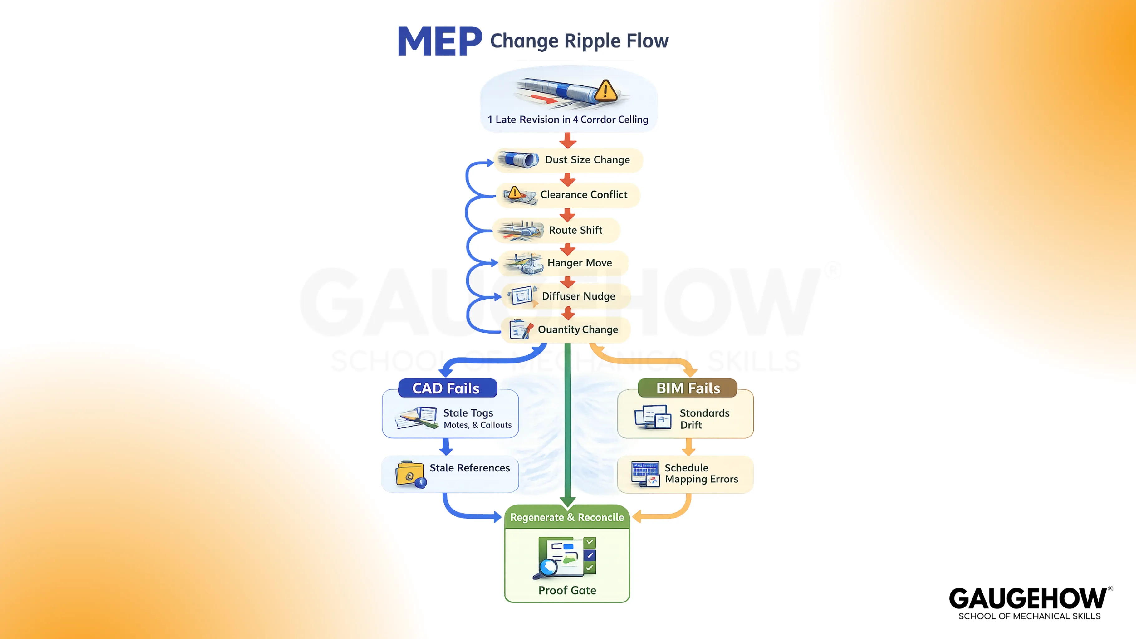
In a drawing-governed workflow, the risk is a stale reference.
A tag can still show the old size.
A note can still describe the old elevation.
A detail callout can still point to a condition that no longer exists.
The team spends time proving nothing was missed, and the miss that hurts is usually small.
In a model-governed workflow, the risk is degraded standards. If families are inconsistent or naming is loose, the schedule can look correct while carrying the wrong mapping, or the view can regenerate while showing the wrong representation.
The team wins when it treats regeneration as a test. Views must read correctly, schedules must reconcile to the changed elements, and coordination checks must pass in the same saved context the team trusts.
When To Use Which
CAD fits when revisions are manageable, and the primary job is documentation. It stays lean when the sheet set is the controlling record and the team has disciplined release habits.
BIM fits when coordination cycles are frequent across architecture, structure, and MEP, and when schedules and quantities must remain aligned with design intent. It pays for itself when one governed source prevents version arguments.
Hybrid fits when coordination must be model-led, but details must stay standardized and reusable.
A hybrid only works when the boundary is explicit. Model outputs cannot be contradicted by drawing fixes, and drawing details cannot quietly redefine coordination intent.
File Formats And Handoff Loss
Most project confusion is not a wrong design.
CAD vs Building Information Modeling: What Survives Export
It means loss during handoff. A file crosses tools, a few assumptions collapse, and the next person builds on something that looks right but is no longer governed.
DWG vs DXF: CAD Geometry Without Identity
When you exchange DWG or DXF, geometry usually survives well, so linework and drafting intent remain readable across platforms. What often does not survive is identity. Elements flatten into shapes and blocks, and that makes downstream interpretation more fragile.
A safe habit is to review the exported file exactly as the receiver will, confirm units, then spot-check a short set of high-risk dimensions and annotations against the issued sheets.
PDF Issue Sets: Frozen Intent, Zero Intelligence
A PDF is the cleanest carrier of issued intent because it freezes what installers and vendors will actually see. That also means it carries almost no intelligence.
You cannot rely on a PDF for editable relationships or reliable takeoff logic. Release discipline becomes the protection here, so you validate revision stamping, sheet index alignment, and a controlled distribution path that prevents old issues from living in parallel.
RVT vs IFC: BIM Exchange And Mapping Drift
Inside a model ecosystem, an RVT keeps the strongest linkage between element identity, parameters, views, and schedules. The risk shows up when publishing is uncontrolled or when recipients consume the information outside that ecosystem.
The professional move is to publish from controlled views and confirm key views and schedules match at the moment of issue, not “close enough in the model yesterday.”
With IFC, the advantage is exchange across platforms, but mapping is the failure mode. Properties can arrive renamed, categories can flatten, and a model can appear visually correct while carrying the wrong semantics under the hood.
A practical check is viewer-based. Confirm category mapping on representative elements, validate levels and locations, then cross-match a small quantity snapshot so procurement-critical numbers do not drift.
Combining BIM And CAD
Draw A Hard Boundary
A hybrid becomes reliable when a new team member can understand the boundary in one minute. One side governs coordination decisions, and the other side governs standardized details.
The boundary is not a preference. It is a control rule that prevents two competing records from existing.
Set A Publish Rhythm
Coordination stays clean when publishing is predictable. A model that updates whenever creates meetings where nobody agrees on what they are looking at.
A drawing set that updates when someone remembers creates site drift. Explicit release points keep downstream users from building from half-updated information.
Treat Exports Like Inspections
Exports are not clerical work. They are inspections for meaning loss.
The safe habit is to review the exported artifact exactly as the receiver consumes it, then cross-match a short list of high-risk items: units, levels, key dimensions, tags, and any schedule or quantity that can trigger procurement errors.
FAQs
Is BIM just 3D CAD?
No. 3D CAD is geometry. BIM is geometry + object identity and data that drive views and schedules.
Does BIM replace CAD?
Not always. CAD stays strong for fast detailing and sheet-first delivery. BIM wins when coordination and data-driven schedules must stay aligned.
Which is better for MEP coordination?
BIM usually wins when coordination cycles are frequent and clashes must be resolved repeatedly, but only when model standards are governed.
What file formats are most common?
CAD commonly exchanges DWG and DXF, and issues PDFs. BIM commonly uses RVT within ecosystems and IFC for cross-platform exchange.
Can you convert CAD drawings into BIM?
You can import geometry, but BIM value comes from rebuilding object identity and parameters. Shapes transfer. Meaning must be authored.
CAD-CAM-CAE Work Platform
Find or Post CAD, CAM and CAE freelance projects, full-time jobs and Internships.
GaugeHow is the platform built for core engineering work. Whether you need a freelancer for a CAD project, a full-time hire, or an engineering intern,post it here and get matched with the right person.


