
CAM Applications: Where It Is Used and How It Works
Learn More in This Video
Subscribe to GaugeHow for More
Computer-Aided Manufacturing, or CAM, is the manufacturing software layer that plans how a part gets machined. It converts CAD geometry into toolpaths, cutting parameters, setup logic, simulation checks, and machine-ready instructions.
Shops use it in CNC production, mold and die work, aerospace components, medical parts, and automotive programs. Teams depend on it because programming gets faster, verification gets stronger, revisions stay cleaner, and machine motion follows a controlled release path rather than manual guesswork.
Read on to see what CAM outputs, where it fits, and when its value rises sharply in real machining work.
What CAM Does In Real Manufacturing
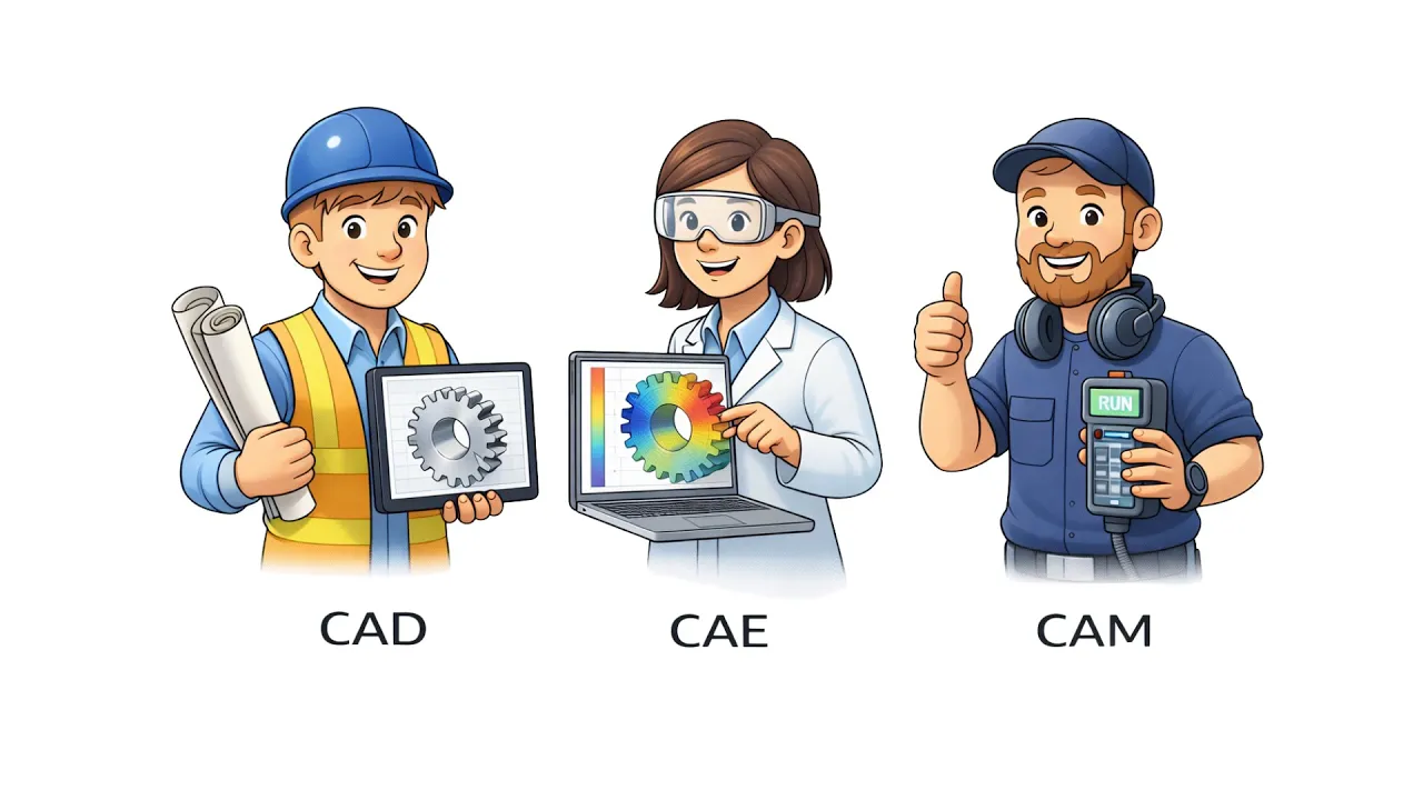
CAM stands for Computer-Aided Manufacturing. In simple terms, it acts as the bridge between design data and machine motion. CAD defines the part. CAM defines how the part gets cut. CNC machines then execute that prepared output on the shop floor.
That distinction matters early because CAM can mean different things in search. Here, it means the manufacturing workflow that supports CNC machines, toolpaths, simulation, and machine-ready instructions. It does not mean a marketing term, a camera term, or a generic applications label.
The software becomes necessary once real shop variables enter the job. Stock condition changes. Fixture access changes. Holder clearance changes. Spindle speed, feed rate, tool changes, and finish targets all change. CAM brings those moving parts into one workflow, so programming follows process logic rather than memory or scattered edits.
What CAM Actually Outputs
CAM does more than generate one block of code. It outputs the machining logic that controls how a part moves from the released model to the machine setup. That includes toolpaths, cutting parameters, operation sequence, simulation checks, and posted machine code for the target controller.
A stronger way to look at it is through deliverables. The programmer is not only drawing cutter motion. The programmer is building a release package for manufacturing.
Tool selection affects load and finish. The setup logic affects reach and stability. Path strategy affects cycle time and proves out. Posted output affects how the controller reads the job.
The most important outputs usually include:
● toolpaths for roughing, semi-finishing, finishing, drilling, and contour work
● cutting parameters such as spindle speed, feed rate, depth, step over, and entry logic
● operation sequence, simulation checks, and posted machine code for release
In advanced workflows, CAM can also support simulation, postprocessing, tooling preparation, and even inspection-related planning. That broader scope makes the page feel complete because modern manufacturing rarely treats path generation as a separate island.
Import CAD Model To Post Process For Release
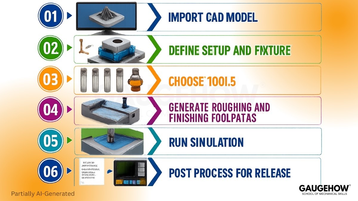
A clean workflow spine makes CAM easier to understand and easier to review.
Import CAD Model
Released geometry enters the system, and feature visibility improves. Programming starts from the approved shape, so revision control stays cleaner.
Define Setup And Fixture
Stock, work offset, fixture position, and machine orientation get locked first. Setting up clarity reduces later surprises and improves handoff quality.
Choose Tools
Tool diameter, reach, holder shape, and cutter type shape the strategy. Better tool choice reduces path problems before simulation begins.
Generate Roughing And Finishing Toolpaths
Material removal strategy gets built around geometry, access, and finish target. Stronger paths reduce air cutting and improve control at the machine.
Run Simulation
Tool motion, holder clearance, and sequence behavior get checked before proving out. Early review drops crash exposure and protects release quality.
Post Process For Release
The software converts strategy into controller-specific output. That final step closes the handoff between programming and live machining.
CAM Applications Across Part Complexity
Part complexity changes how much responsibility CAM carries. Simple parts need clean sequencing and reliable toolpaths. Surface heavy parts need smoother motion and tighter finish control. Multi-face parts add orientation, reach, and collision pressure. That is where CAM applications become a process control layer rather than a convenience tool.
Simple Prismatic Parts
Brackets, plates, housings, and fixture blocks usually need facing, holes, pockets, and contours. CAM speeds those jobs by organizing tool order, path sequence, and setup logic in one place. Programming gets faster, and proving out becomes easier to control.
Contour Heavy Mold Surfaces
Cavities, cores, ribs, shutoff faces, and deep pockets place more pressure on path quality. Tool contact has to stay smooth, and step over has to stay controlled. Better finishing paths improve surface quality, polishing drops, and release moves faster.
Multi-Face Complex Parts
Blisks, impellers, thin-wall brackets, and implant style contours demand stronger planning. Tool angle, reach, and holder position all influence the path. More stable motion lowers prove out risk, and scrap exposure falls before expensive cuts begin.
Part Type | CAM Need | Machine Complexity | Main Output | Proof Check |
Bracket or housing | Pocket and contour control | Low to medium | 2D and 3D toolpaths | Stock and offset review |
Mold cavity | Surface and finish planning | Medium to high | Roughing and finishing paths | Holder and collision check |
Thin-wall aerospace part | Stable access and sequence control | High | Multi-sided machining path | Simulation and stability review |
Precision contour part | Fine contact and small tool control | High | Tight finish strategy | Surface and tolerance review |
How CAM Supports CNC Machining
Strong CNC machining depends on output that matches the stock, fixture, tool, and controller reality. CAM supports that chain by connecting geometry to coordinates, setup, operation order, spindle speed, feed rate, tool changes, and posted output.
Programming starts with strategy. Roughing removes stock under controlled load. Semi-finishing prepares the surface for final passes. Finishing protects tolerance and surface quality. Drilling handles depth, retraction, and cycle behavior.
CAM keeps those actions linked, so the machining plan follows one release path rather than disconnected decisions.
The next gain appears during the prove out. Unsafe entries, weak retracts, missed stock, and wasted air moves show up before the machine starts cutting.
That early visibility protects fixtures, holders, cutters, and spindle time. It also improves the handoff because operators can review the intended sequence before live motion begins.
When 5-Axis Machining Changes The Programming Logic
Complex surfaces expose the real value of 5-axis machining. One setup can reach more faces, but that freedom raises the programming load. Tool angle, holder clearance, machine travel, and transition control all become part of the release logic.
Once 5-axis machining enters the job, the software has to manage more than cutter location. It has to optimize orientation, avoid collisions, and smooth motion through changing surfaces. Better angle control improves reach, fewer re-clamps reduce stacked error, and finish quality stays more stable across the part.
The key programming shifts usually look like this:
● The tool angle must protect reach, surface contact, and holder clearance
● Transition control must keep the motion smooth and avoid finish damage
● The simulation must confirm machine limits before the release reaches production
Multi-axis work rewards disciplined planning. CAM gives a planning structure that the machine, the programmer, and the setup team can all trust.
Where CAM Is Used By Industry
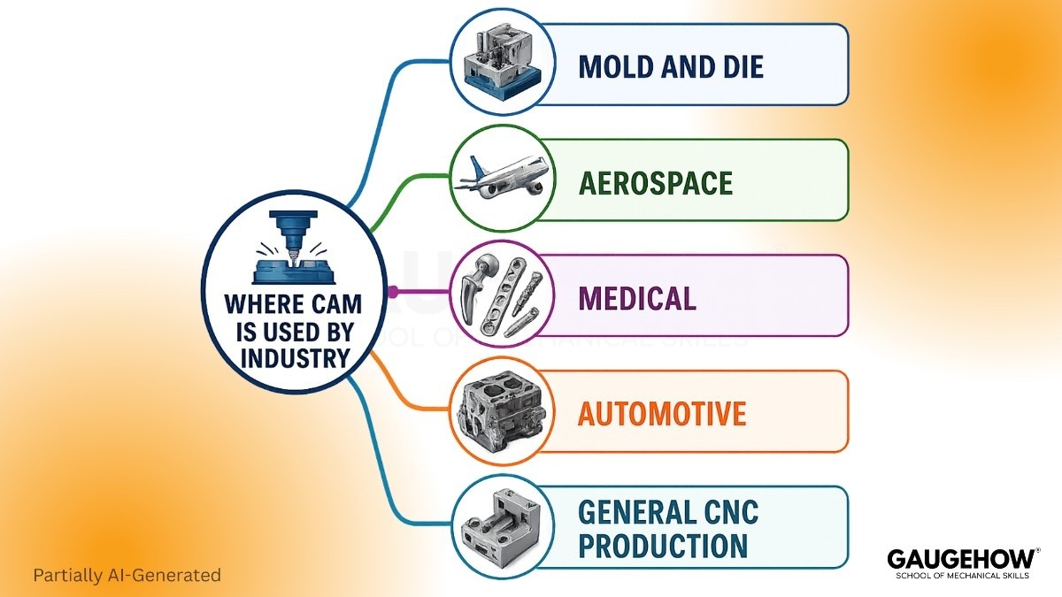
Different sectors rely on CAM for different reasons, but the pattern stays the same. Geometry gets harder, tolerance pressure rises, and machine time becomes too expensive for manual guesswork. That is where CAM applications create direct production value.
Mold And Die
Mold and die shops use CAM for cavities, cores, ribs, shutoff faces, inserts, and deep contour work. Surface quality drives downstream part quality, so the finishing path has to stay controlled through the full cavity. Cavity finishing gets smoother, polishing drops, and release becomes faster.
Aerospace
Aerospace teams use CAM on blisks, housings, brackets, thin-wall structural parts, and contour-driven components. Material cost runs high, and path instability can damage both stock and schedule. Thin wall brackets get safer paths, prove out risk drops, and scrap risk falls.
Medical
Medical production uses CAM for implants, surgical tools, bone plates, and small, contour-heavy parts. Tiny tools and fine finish targets leave little room for weak path control. Small precision parts get a cleaner motion, repeatability improves, and batch release stays more stable.
Automotive
Automotive work uses CAM on dies, fixtures, engine parts, transmission components, and repeat production features. Revision speed matters here because programs often evolve under production pressure. Toolpath reuse gets stronger, cycle control improves, and release updates move faster through the shop.
General CNC Production
General job shops and machine builders use CAM for plates, housings, brackets, shafts, fixtures, and custom one-off parts. Work changes often, so programming needs flexibility without losing discipline. Mixed part families get cleaner handoff, setup confusion drops, and output stays more consistent.
Most Asked Questions
What Is CAM Used For In Manufacturing?
CAM is used to create machine-ready cutting instructions. It generates toolpaths, cutting parameters, and operation order so programming moves faster, proving out gets safer, and the released output matches setup conditions.
Is CAM Only Used For CNC Machines?
CAM is not limited to running CNC machines alone. It also supports setup planning, simulation, postprocessing, tooling preparation, and revision control before the controller receives machine code for live cutting work.
Why Is CAM Important In Mold And Die Work?
CAM is important in mold and die work because cavities and cores need smooth toolpaths. Better path control improves surface quality, reduces polishing effort, and shortens the prove-out before release.
How Does CAM Help Aerospace And Medical Parts?
CAM helps aerospace and medical parts by controlling harder geometry and smaller tools. Stronger simulation, holder clearance checks, and path stability reduce scrap exposure and protect precision during prove out.
What Is The Difference Between CAD, CAM, And CNC?
CAD creates the part geometry and design intent. CAM creates the machining logic and release output, and CNC machines execute that output through controlled motion at the machine tool.
Mechanical Engineering Courses That Industry Actually Uses
Learn Tools of Design & CAD, Analysis & Simulation, Automation & Robotics, and Industry 4.0 used in modern factories.
Join 40+ Mech Courses like GD&T, Siemens NX, SolidWorks, CATIA V5, AutoCAD, ANSYS (FEA & Fluent), ABAQUS, Creo, Fusion 360, CNC Programming, Digital Twins, Python for Mechanical, and Industry 4.0.
Our Courses
Complete Course Library
Access to 40+ courses covering various fields like Design, Simulation, Quality, Manufacturing, Robotics, and more.


