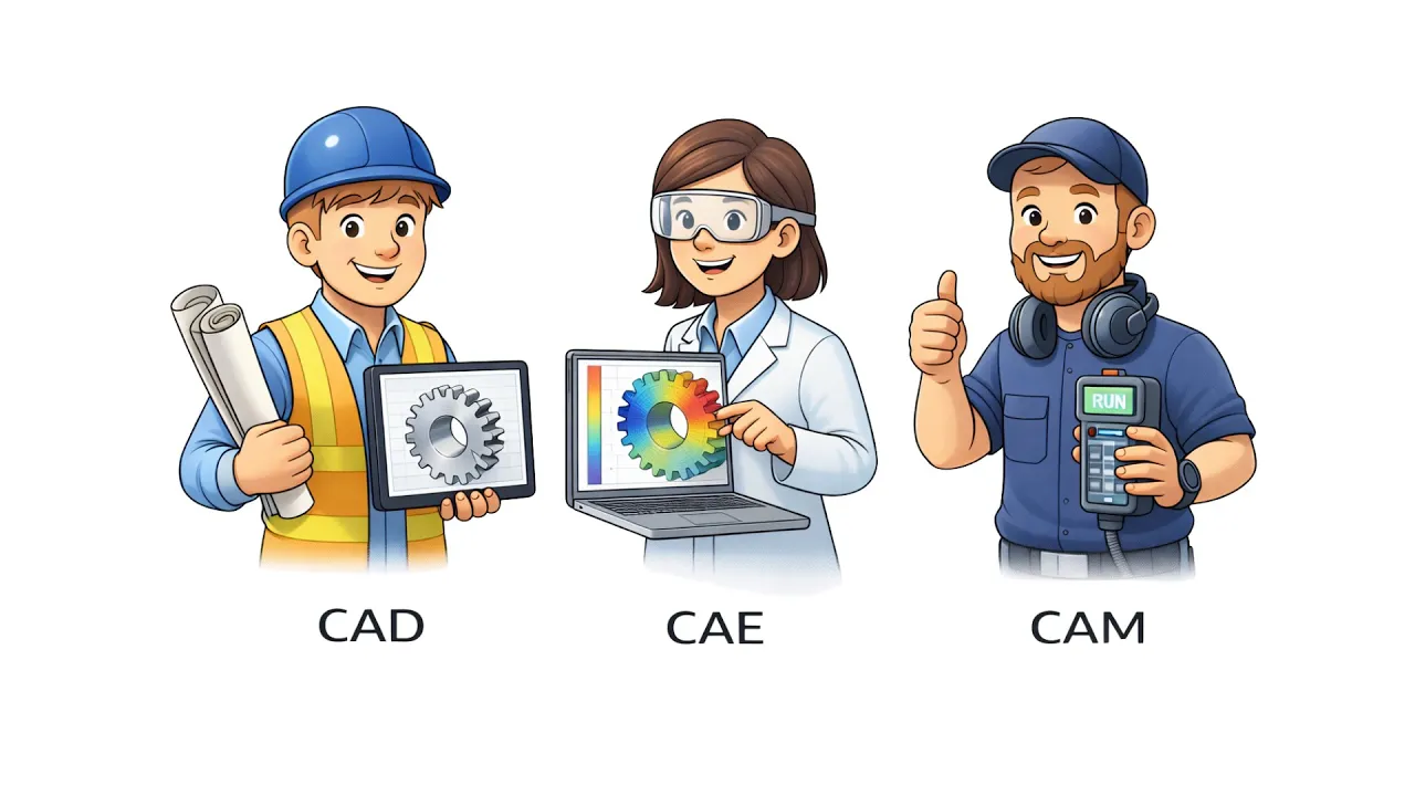

CAM vs CNC: What’s the Difference and Where Each Starts
Learn More in This Video
Subscribe to GaugeHow for More
CAM creates toolpaths, selects operations, and outputs machine-ready instructions. CNC reads those instructions through the controller, applies offsets, drives axis motion, manages tool changes, and cuts the part.
Start with geometry, develop the process, convert the output, set the machine, run the cycle, and verify the result.
A drawing defines size, depth, profile, hole location, and tolerance. Process planning converts those features into roughing paths, finishing paths, drilling cycles, spindle speed values, feed rate values, and clearance moves.
Program output passes through a post-processor and reaches the controller in machine-readable form. Work offsets place the stock in machine coordinates. Machine tools follow the program.
Inspection confirms whether execution matched design intent.
Manufacturing logic makes the distinction clear. CAM develops the cutting process before the spindle starts.
CNC controls the physical cut after the program reaches the machine. One side creates machining intent. One side executes the machining intent. Clear sequence turns both terms into one readable system.
What Is CAM vs CNC?
CAM vs CNC is the difference between digital process creation and machine-side execution.
CAM creates the machining strategy for each feature. Operations define which end mill cuts the pocket, which drill opens the hole, which pass roughs the wall, and which pass finishes the surface.
Toolpaths control cutter motion, entry direction, retract height, and sequence. The program output prepares those decisions for the target control.
CNC executes the strategy on hardware. The controller reads the code, moves the axes, starts the spindle, manages coolant, handles tool changes, and removes material from stock. Machine motion turns planned operations into a real pocket, a real hole pattern, and real profile.
Workflow position separates both terms cleanly. Planning belongs to CAM. Execution belongs to CNC.
Cut strategy, simulation, and output development happen before setup. Clamping, offsets, dry cycle checks, spindle load, and first-piece behavior belong to execution.
Role/Task | Output | Tools | Downstream Use | Proof Check |
Create feature strategy and cutting sequence | Toolpaths and machine-ready program output | Model, operation setup, tool library, post-processor | Sent to the controller for execution | Simulation, clash check, path review |
Execute the programmed process on hardware | Pocket, holes, profile, finished surfaces | Controller, spindle, machine tools, fixtures, coolant | Produces the physical part | Dry cycle, first-piece check, dimensional measurement |
Verify the finished part | Accepted size, depth, location, and finish | Vernier, micrometer, bore gauge, CMM | Confirms release or correction | Tolerance check, repeatability check |
CNC follows the path.Direct rule helps here. CAM creates the path.
Why Do We Need Both?
Geometry does not cut stock. Machine motion does not design the process. Manufacturing needs both stages because each one controls a different part of the result.
Feature planning decides how the cut should happen. A pocket needs a cutter diameter, depth strategy, stepdown, stepover, entry move, retract level, and finishing allowance.
Roughing removes material fast. Finishing controls size and surface quality. Process design shapes tool life, cycle time, stability, and feature accuracy long before chips form.
Execution controls whether the plan survives contact with the machine. Fixture position, stock seating, work offsets, tool length values, spindle condition, coolant reach, and machine state all affect the actual cut.
Correct output with poor setup still creates scrap. Strong setup with weak planning still wastes time and may damage finish or overload the cutter.
Risk also splits across both stages. Planning controls path quality, operation order, and machining logic. Execution controls motion accuracy, hardware behavior, and physical repeatability. Final part quality depends on both sides holding together from output creation through measurement.
Where CAM Software Fits in the Workflow
Feature definition comes first. Geometry may arrive from a 3D model, a 2D drawing, or a revision of an older part. CAM enters after that stage and develops the cutting process.
CAM software creates operations around each feature. Stock definition sets the starting material. Coordinate setup establishes the work origin. Tool selection assigns the right end mill, drill, or face tool.
Operation settings control pocketing, contouring, drilling, roughing, and finishing. Toolpaths define how each cutter approaches, cuts, retracts, and clears surrounding geometry.
Practical value appears in the decisions it makes visible. A rectangular pocket may need one roughing path to remove bulk material and one finishing path to control wall size.
Deep geometry may require multiple stepdowns. Small corner radii may force a smaller end mill. Tight tolerance may require lighter finishing passes. A shorter cycle time may need path optimization without sacrificing stability.
Simulation provides another layer of control. Clearance moves can be checked. Holder interference can be evaluated. The remaining stock can be reviewed. The operation order can be optimized. Machine tools do not see the part yet, but the digital process already exposes risk before setup begins.
Output from this stage is not the finished part. Output from this stage is a validated cutting process ready for conversion into machine-readable code.
Where CNC Programming Basics Start
Program output reaches the machine first. The setup discipline starts immediately after that point.
CNC programming basics begin where controller logic, machine coordinates, work offsets, tool tables, spindle commands, coolant commands, and fixture position all meet the program. Every instruction now depends on real hardware conditions.
Program loading is only the first step. Stock must be clamped securely. Datum location must match the programmed origin. Tool length values must match the loaded holders.
Tool numbers must match the intended stations. Coolant flow must support the cut. Travel direction must clear the fixture. Controller state must match the sequence expected by the code.
Setup errors raise execution risk quickly. An offset error shifts the pocket and hole pattern in machine coordinates. A tool-length error drives the end mill too deep into the stock.
An incorrect tool-change command sends the wrong cutter into the cut. Loose workholding lets the blank move under the cutting load. Poor coolant flow harms surface finish and reduces tool life.
A dry run protects the first cycle. It checks clearance, retract height, and controller response before cutting load reaches the spindle. Feed override lets the operator review critical toolpaths safely.
First-piece inspection checks chip flow, spindle sound, pocket depth, and feature quality. Correct code alone does not guarantee a correct part. Accurate setup keeps machine motion aligned with design intent.
How G-code Connects Planning to Motion
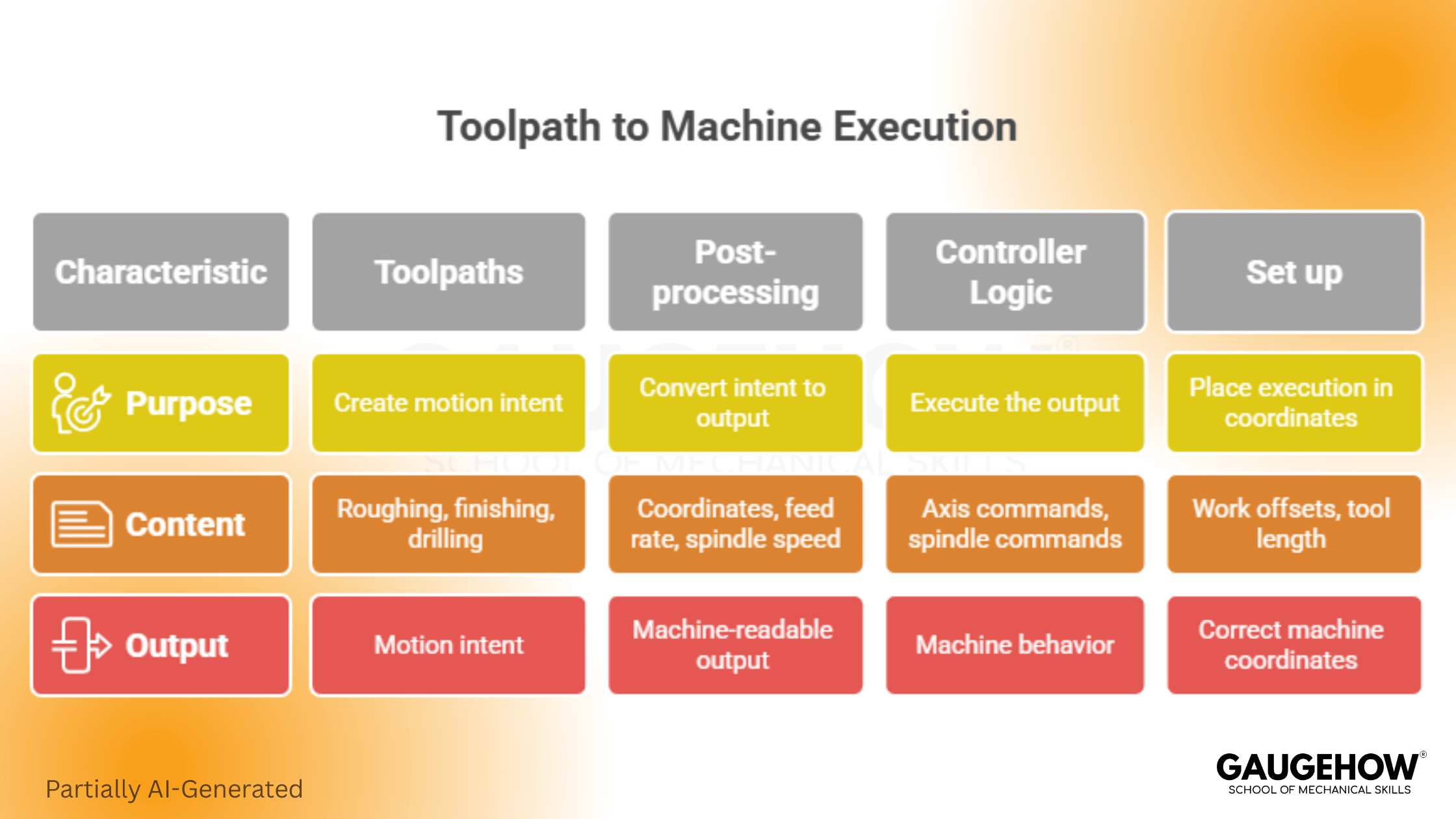
Toolpaths exist first as machining logic. Code exists next as controller-readable instruction. Motion exists last as machine behavior. That chain is the real handoff.
G-code carries coordinates, feed rate commands, spindle speed commands, tool changes, coolant calls, and motion instructions from process planning into the controller.
A post-processor converts the developed toolpaths into the format required by the target control. Controller logic reads each line, activates machine functions, and drives axis movement through the programmed sequence.
Four stages define the bridge clearly.
1. Toolpaths create motion intent
Roughing path, finishing path, drilling cycle, lead-in, lead-out, retract level, and clearance logic are all created before posting.
2. Post-processing converts motion intent into machine-readable output
Coordinates, feed rate values, spindle speed values, coolant commands, pauses, and tool changes are formatted for the intended control.
3. Controller logic executes the output
Axis commands move the cutter. Spindle commands drive rotation. Tool change calls swap holders. Coolant commands support cutting conditions.
4. Set up places execution in the correct machine coordinates
Work offsets align stock location with the program. Tool length values align cutter position with the path. Fixture position determines whether the path clears real hardware.
Strength of this section comes from separation. CAM software creates toolpaths and output. Post-processing converts paths into machine-readable code.
Controller logic follows those instructions. Setup decides whether execution matches intent. Inspection confirms whether the feature reached size, depth, and location.
Breaks in that bridge create predictable problems. Incorrect post output can mismatch control format. Correct code with a wrong offset can cut air or crash a vehicle. Stable motion with worn tools can missize.
Strong geometry with poor coolant flow can damage finish. Measurement closes the chain by checking whether the real cut matched the required feature.
From Drawing to Inspection: One Real Part
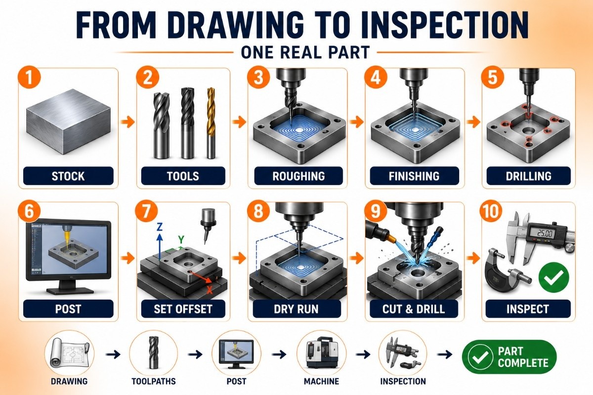
The aluminum plate example makes the sequence visible. Part drawing calls for one outer profile, one central pocket, and four holes on a bolt pattern. Each step changes the workflow in a practical way.
1. Choose stock
Raw material size must provide clamping allowance and enough thickness for facing and final feature depth.
2. Choose the cutters
Pocket shape may need one end mill for roughing and one tool for cleaner finishing. Hole size selects the drill. Edge quality may influence the final profile tool.
3. Create the roughing path
Operation setup defines pocket boundaries, stepdown, stepover, entry motion, and stock allowance left on walls and floor.
4. Create the finishing path
Lighter passes develop final wall size, final pocket depth, and cleaner surface condition.
5. Create the drilling cycle
Hole positions use programmed coordinates tied to the part datum. Feed rate and spindle speed values support the chosen drill and material.
6. Post the program
Post-processor converts all developed paths into controller-readable output with motion commands, tool changes, coolant calls, and sequence order.
7. Set the work offset
Machine coordinates must align with the program origin. Fixture position and stock location determine whether the path lands on the real feature.
8. Run the dry cycle
Clearance height, retract moves, tool changes, and operation sequence are checked before full cutting begins.
9. Cut the pocket and drill the holes
Spindle speed, feed rate, coolant, sound, chip flow, and load behavior are observed during execution.
10. Verify the finished features
Pocket depth is measured. Hole location is checked. Profile size is confirmed. Surface finish is reviewed. Inspection decides release or correction.
Process proof sits inside that sequence. Drawing defines intent. Toolpaths develop the cut. Post-processing converts the output. Controller logic drives motion. Setup aligns the machine. Inspection validates the result.
Which Side Starts First in Real Work?
Process question determines the starting side.
Feature strategy starts on the planning side. Cutter selection, roughing method, finishing method, stepdown, stepover, feed rate, spindle speed, and cycle optimization all belong to process development.
Revision changes also begin there because geometry or tolerance changes often require new toolpaths or different tool choices.
Execution question starts on the machine side. Workholding, offset position, tool table accuracy, coolant direction, travel limits, spindle condition, and first-piece safety all belong to setup and control. Machine behavior becomes the focus once output reaches hardware.
Normal manufacturing order still follows one sequence. Planning starts first. Execution starts after posting and setup. Final proof comes from inspection. Strong understanding comes from tracking that order without mixing the roles.
FAQs
What is the difference between CAM and CNC?
CAM creates the cutting process and output. CNC executes that output through the controller, spindle, machine tools, and setup system.
Does CAM software create G-code?
CAM software creates toolpaths and operation logic. Post-processing converts that output into machine-readable code for the controller.
Can a correct code still produce a wrong part?
Yes. Wrong offsets, wrong tool length values, poor workholding, worn cutters, or poor coolant conditions can still shift size, depth, location, or finish.
Where do feed rate and spindle speed fit?
Planning develops those values around tool choice, material, and operation type. Execution applies those commands through the controller and spindle during the real cut.
Which side should a beginner learn first?
Workflow understanding should come first. Feature definition, toolpaths, post-processing, controller logic, setup, and inspection form the clearest learning order.
Mechanical Engineering Courses That Industry Actually Uses
Learn Tools of Design & CAD, Analysis & Simulation, Automation & Robotics, and Industry 4.0 used in modern factories.
Join 40+ Mech Courses like GD&T, Siemens NX, SolidWorks, CATIA V5, AutoCAD, ANSYS (FEA & Fluent), ABAQUS, Creo, Fusion 360, CNC Programming, Digital Twins, Python for Mechanical, and Industry 4.0.
Our Courses
Complete Course Library
Access to 40+ courses covering various fields like Design, Simulation, Quality, Manufacturing, Robotics, and more.


