G-Code vs M-Code: What They Control and How CAM Generates Them
Learn More in This Video
Subscribe to GaugeHow for More
G-code controls tool motion and cutting path. M-code controls spindle, coolant, tool change, and program state. CAM is generated both through the operation setup and post output. Posted code then changes by controller because each control expects a different format, command style, and file structure.
Clear code reading starts with control separation. G-code drives movement. M-code drives machine actions around movement. CAM defines machining intent, then a post turns that intent into an NC file. Controller logic shapes final syntax, so one posted program does not suit every machine.
G-Code vs M-Code
G-code and M-code work together inside one CNC program, but each controls a different layer. G-code handles path logic, position logic, coordinate handling, and cycle behavior. M-code handles spindle state, coolant state, tool change, stops, and program end. Once that split is fixed, program reading becomes much cleaner.
Program review improves when each line is read by control role. Motion commands answer one question. Where does the tool move next? Machine commands answer another question. What must the machine do before, during, or after that move? Good reading starts by separating those questions.
What G-Code Controls
G-code controls rapid moves, linear moves, circular moves, plane selection, units, work offsets, and canned cycles. Geometry depends on those commands because they define how the tool travels through space. A wrong motion code changes path shape, entry style, or location.
Programming consequence is direct. Path logic errors create wrong features, wrong depth approach, or wrong cycle behavior. Review value is also direct. Strong G-code reading catches path problems before release.
What M-Code Controls
M-code controls machine behavior around cutting. Spindle start, spindle stop, coolant on, coolant off, tool change, optional stop, and program end all sit under M-code. No axis path is defined there, but machining cannot run correctly without those machine actions.
Programming consequence is just as important. Wrong spindle state ruins cutting conditions. The wrong coolant state affects chip control and finish. Wrong tool change order breaks operation sequence and review confidence.
Control Area | G-Code | M-Code | Review Focus |
Motion | Yes | No | Path and position |
Machine state | No | Yes | Spindle, coolant, tool change |
Geometry effect | Direct | Indirect | Feature accuracy |
Sequence effect | Strong | Strong | Release logic |
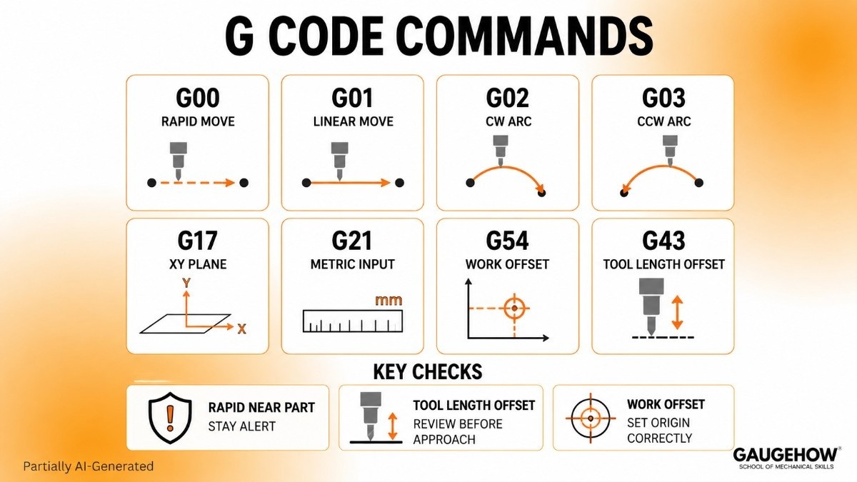
G Code Commands
A strong page should not bury readers in a giant list. A shorter command set teaches faster because each entry stays tied to machine effect and review value.
● G00 sets rapid positioning between points. The machine moves fast without cutting.
● G01 sets straight cutting motion. Tool follows a controlled linear path.
● G02 sets clockwise arc motion. Circular interpolation begins in active plane.
● G03 sets counterclockwise arc motion. Arc direction changes path result.
● G17 selects the XY plane. Arc and cycle behavior follow that plane.
● G21 selects metric input. Coordinate values follow the millimeter scale.
● G54 selects a work offset. The program coordinates a shift to set up the origin.
● G43 applies tool length offset. Z movement follows the measured tool length.
A useful G code list should always answer machine effect first. Command meaning becomes easier when linked to tool motion, coordinate behavior, and setup origin. A shallow label-only list does not teach enough for review.
Path control also carries release value. G00 near a part edge needs more attention than G00 in open air. G43 needs review before approach moves because tool length changes Z interpretation. Small commands can carry big consequences.
M Code Commands
Machine-side commands deserve equal attention because they control readiness, state, and cycle closure. A short list with clear effects teaches more than a long controller dump.
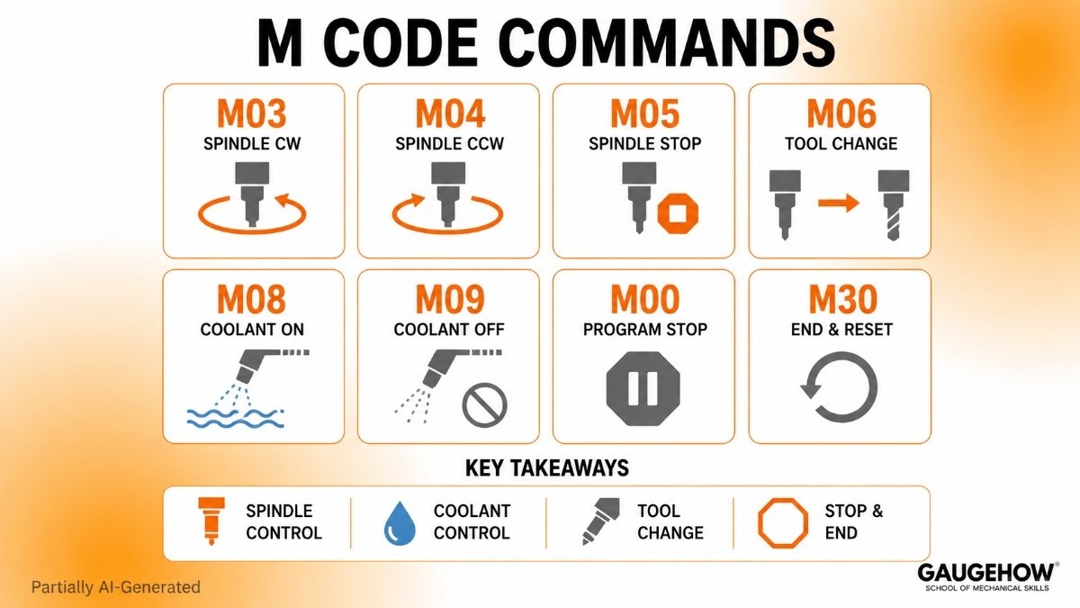
● M03 starts spindle clockwise. Cutting can begin once speed is active.
● M04 starts spindle counterclockwise. Rotation direction changes for specific tools.
● M05 stops spindle rotation. Machine leaves cutting state.
● M06 loads a tool. Operation changes to a new cutter.
● M08 turns coolant on. Chip evacuation and heat control begin.
● M09 turns coolant off. Program leaves coolant state.
● M00 makes a programmed stop. Review or intervention can follow.
● M30 ends and resets program. Control returns to program start state.
A practical M code list should show machine action, not just code names. Spindle state, coolant state, and tool change order shape program readiness. Clear reading of those commands improves setup review and handoff clarity.
Machine commands also change depending on the controller and machine option. Common entries stay familiar, but exact behavior can still vary. Final review should always follow target control, not a generic internet list.
CAM to NC Code
CAM should be explained as output logic, not software promotion. Good CAM writing answers four questions only. What does CAM decide? What does the post add? What does the NC file contain? What still needs an engineer's judgment?
What CAM Decides
CAM decides setup origin, stock relation, tool selection, operation sequence, cut direction, stepovers, depths, links, retracts, and feed values. Those choices create machining intent before any posted file exists. Toolpaths are a result of operation logic and selected settings.
Programming consequence is strong here. Clean setup creates clean output. Weak setup creates weak output even with polished software screens. Review value starts before posting, not after posting.
What Post Adds
A post-processor converts CAM intent into control-specific code. File structure, header style, offset calls, canned cycle format, coolant syntax, and program end style are shaped there. Same toolpath can produce different code once a different post-processor is selected.
Controller fit is main reason. CAM creates a general machining intent. Post output creates machine-ready language. That is why code from one post should not be assumed safe for another machine.
What NC File Contains
A final NC file contains tool calls, spindle commands, work offset calls, tool length offset lines, motion blocks, feed values, coolant commands, retract logic, and program end lines. Those are CNC machine commands arranged in a sequence meant for one specific control.
NC output should be read as an engineering deliverable, not a software export. Program order, active states, and controller expectations all deserve attention before approval.
Posted Code Review
A page on G-code vs M-code needs a real block breakdown. Line-by-line reading teaches more than repeated definitions because the command order becomes visible.
Line One
T1 M06 calls Tool 1 and executes a tool change. Machine effect is immediate. Control prepares a new cutter for the next operation. The programming consequence is simple. Every later motion line now belongs to Tool 1 unless another tool call appears.
Line Two
S2500 M03 sets the spindle speed to 2500 and starts clockwise rotation. Machine effect is spindle readiness for cutting. Programming consequence is also clear. Any entry move after this line assumes a live spindle at commanded speed.
Line Three
G54 G00 X0 Y0 selects work offset G54 and rapids to X0 Y0. Machine effect is a position change in active setup coordinates. Programming consequence is strong because all later coordinates are now tied to G54, not machine home.
Line Four
G43 H01 Z50 applies tool length offset H01 and moves to Z50. Machine effect is corrected Z position based on measured tool length. Programming consequence is critical because Z travel now reflects actual tool geometry.
Line Five
G01 Z-5 F120 makes a controlled cutting move to Z-5 at feed 120. Machine effect is entry into material or approach to the cut depth. Programming consequence depends on all earlier lines being correct.
Review usefulness comes from reading block order, not isolated commands. Tool call before length offset. Spindle start before feed move. Work offset before entry location. That order gives a dependable reading method.
● Read work offset before entry move.
● Read tool call before length offset.
● Read spindle state before cut starts.
● Read coolant and retract logic near cycle changes.
● Read end blocks before release.
Those review rules help junior engineers move from code recognition to code judgment. Recognition sees commands. Judgment sees program intent.
Controller Code Differences
Controller differences deserve a full section because the posted code is never fully universal. The same toolpath intent can still produce different file formats, canned cycle styles, header logic, and offset structure across controls.
Same Intent, Different Code
CAM output may drill one hole pattern on two machines, but posted syntax can still change. One control may prefer a certain cycle format. Another may output separate lines or different modal behavior. Toolpath intent stays constant, while posted language changes.
The programming consequence is obvious. A correct toolpath does not guarantee a correct file for every machine. Review value rises once controller logic is treated as part of program approval.
Why Format Changes
Controller architecture, supported cycles, offset style, and machine options all shape posted code. A file prepared for one environment carries assumptions about command order, active states, and accepted syntax. That is why CNC machine commands should always be read inside a controller context.
CAM Limits and Engineer Decisions
Strong pages should not stop at software output. CAM generates path logic. CAM does not own full machining intent. Geometry does not define every safe start condition. The posted code still needs a release judgment. Command order changes machine behavior, not just file appearance.
What CAM Cannot Decide?
CAM does not fully know shop standards, release priorities, setup habits, or the preferred startup sequence. Stock position may be correct in CAM and still need a different entry plan on a real machine. An operation order may look efficient on screen and still need a different handoff decision.
What Engineers Must Decide
Engineers still decide whether the command order is clear, whether the startup state is complete, whether offset calls suit setup, whether retract style is sensible, and whether release notes match program intent. A good review completes CAM output rather than competing with it.
That section is where senior value appears. Definitions teach language. Decisions teach responsibility. Good blogs should teach both.
FAQ
What is G-code vs M-code?
G-code controls movement, path type, work offsets, and cycle behavior inside a CNC program. M-code controls spindle, coolant, tool change, stops, and program end. Both command families work together, but each owns a different control role.
What do G-code and M-code control?
G-code controls motion and geometry-related behavior such as rapid moves, feed moves, arcs, planes, and offsets. M-code controls machine actions such as spindle rotation, coolant state, tool change, stop functions, and reset behavior.
How does CAM generate both?
CAM creates setup logic, tool data, cut sequence, and toolpaths first. A post-processor then converts that machining intent into controller-ready code, including motion commands, machine commands, offsets, program structure, and end-of-program logic.
Why does posted code change by controller?
Posted code changes because each controller expects its own syntax, cycle style, header logic, offset calls, and file structure. Same machining intent can stay valid while final code still changes across machine environments.
What should beginners review first?
Start with work offset, tool call, spindle state, tool length offset, entry move, feed move, coolant state, and end lines. That order builds a dependable reading habit and improves release confidence much faster.
Mechanical Engineering Courses That Industry Actually Uses
Learn Tools of Design & CAD, Analysis & Simulation, Automation & Robotics, and Industry 4.0 used in modern factories.
Join 40+ Mech Courses like GD&T, Siemens NX, SolidWorks, CATIA V5, AutoCAD, ANSYS (FEA & Fluent), ABAQUS, Creo, Fusion 360, CNC Programming, Digital Twins, Python for Mechanical, and Industry 4.0.
Our Courses
Complete Course Library
Access to 40+ courses covering various fields like Design, Simulation, Quality, Manufacturing, Robotics, and more.


