
CAM Software: Toolpaths, Workflow, and CNC Output
Learn More in This Video
Subscribe to GaugeHow for More
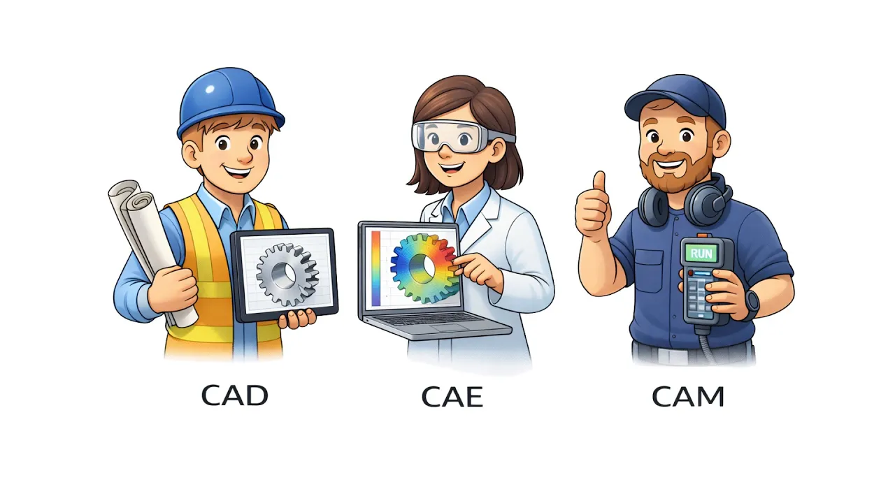
CAM software turns CAD geometry into machining logic that a CNC machine can execute. It sits between design and machining because a model alone does not define stock condition, setup reference, toolpath order, or controller behavior.
Inside CAM, toolpaths describe cutter motion, transition moves, holder clearance, and engagement strategy. Post-processing then converts that internal logic into controller code.
The controller executes the final program through active mode, work offset, spindle state, and machine response. That chain is why CAM affects machining quality long before metal is cut.
Design data becomes useful only after manufacturing intent is added. A pocket in CAD is still just geometry.
CAM assigns stock, datum direction, cutters, feeds, speeds, transition moves, and sequencing, making the feature machinable rather than merely visible. Once that logic is structured well, review effort drops and release confidence rises.
What Is CAM Software?
CAM software is the process layer that turns design geometry into an executable machining plan.
It defines setup logic, operation order, cutter motion, transition behavior, verification steps, and machine-ready output, so production can move from model to control without rebuilding intent at the machine.
That role changes programming quality immediately. A clear CAM plan reduces manual path building, making the sequence more consistent across jobs. A structured CAM plan also reduces hidden interpretation, so toolpath behavior is easier to review before prove-out begins.
CAM Between CAD And CNC
CAD defines shape, dimensions, and feature relationships.
CAM interprets that geometry through stock condition, tooling, and machining strategy, so the part can move from design space into process space. Without that layer, CNC receives form but not manufacturing logic.
That gap matters because controls do not execute models. Controls execute instructions.
CAM fills that gap by translating design features into toolpath intent, setup reference, and output structure, which is why it belongs squarely between CAD and CNC rather than beside them.
What CAM Software Produces
CAM software produces more than a path on screen.
It generates operation trees, tool libraries, stock definitions, simulation results, setup sheets, and post-processed output, so programming decisions can move cleanly into checking and release.
Each output changes a different stage of work. Setup sheets improve preparation. Simulation improves review.
Controller-ready code improves execution. Because all three travel downstream, CAM shapes far more than the file that finally reaches the control.
What CAM Does Not Decide
CAM does not own the final judgment over release quality.
Datum choice, sequence risk, work offset strategy, revision validity, and live machine condition still need engineering review, so a correct toolpath can still lead to weak execution when the context is wrong.
That boundary needs to be explicit early. Once software is treated as a decision engine without limits, output gets trusted more than it should.
Once software is treated as a planning system inside a larger release process, checking becomes sharper and downstream errors become easier to catch.
Why CAM Matters In CNC Work
CAM matters because it compresses path planning into a repeatable process.
Instead of rebuilding motion block by block, geometry, tooling, and sequence can be organized in one environment, so programming speed rises while path consistency improves.
A second advantage appears during revision work. Model changes can be pushed back through operations, simulation, and output with far less manual rebuilding.
That reduces rework time and keeps process control tighter when drawings or part conditions change midstream.
How Does CAM Software Work?
CAM software works as a workflow, not as a feature list.
Geometry comes in first. The setup logic is defined next.
Tools and operations are assigned after that. Simulation verifies behavior.
Post-processing creates controller code at the end. Because each stage feeds the next one, weak decisions upstream usually become expensive decisions downstream.
Import CAD Geometry
Imported geometry becomes the basis for every later decision.
Surfaces, features, stock allowance, and revision status define what the software thinks the part is, so the first import step already influences path structure and output confidence.
A wrong model creates a silent failure chain. Stock may be assigned incorrectly. Operation boundaries may drift.
Output can still post cleanly while the part intent is already broken. That is why geometry import is not housekeeping. It is the first quality gate.
Define Setup And Stock
The setup definition gives CAM its machining frame of reference.
Datum direction, setup reference, stock shape, fixture orientation, and work offset assumptions all enter here, so the software can calculate motion in a way that matches real fixturing.
Those choices control more than the part location. Tool access, spindle orientation, transition length, and holder clearance all depend on setup logic.
Once setup is wrong, the simulation may still look acceptable, while the live machine behavior becomes awkward or unsafe.
Select Tools And Operations
Tool selection defines engagement conditions before motion is calculated.
Cutter diameter, holder shape, flute length, feed, speed, and operation order all shape how the toolpath will behave, so the operation list is already a process plan rather than a menu of moves.
The sequence also changes the part stability. One order may protect geometry and stock condition for later cuts. Another may expose thin features too early or leave awkward stock islands for finishing.
Tool choice and operation order, therefore, deserve joint review, because both control the same mechanical outcome.
Simulate And Verify
Simulation turns internal logic into visible machine behavior.
Holder clearance, overtravel, leftover stock, gouging risk, and transition moves can be inspected before output is released, so uncertainty is pushed earlier, where correction is cheaper.
That shift changes review quality. Problems seen in the simulation can be fixed in the software with full context.
Problems first seen at the machine arrive late, where setup time is already spent, and machine response is less forgiving.
How Are CNC Toolpaths Created?
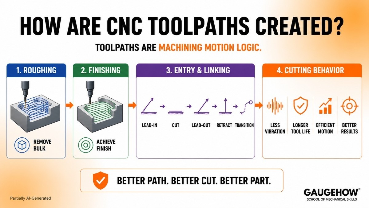
Toolpaths are not decorative lines.
Toolpaths are machining motion logic shaped around stock condition, cutter geometry, entry style, linking behavior, and surface intent.
Because the toolpath is what the cutter actually follows, path design controls physical cutting behavior long before a controller ever reads a program block.
Roughing Toolpaths
Roughing toolpaths remove bulk material while preserving a manageable load and predictable stock condition.
Engagement angle, stepdown, stepover, and transition strategy all control how material is opened up, so roughing is really about controlling remaining material as much as removing existing material.
That outcome reaches deeper into the job than roughing speed alone. A stable roughing strategy leaves consistent stock for finishing, so later passes inherit cleaner conditions.
An unstable roughing strategy leaves irregular stock, so finishing inherits inconsistency, and tool load becomes harder to manage.
Finishing Toolpaths
Finishing toolpaths control final geometry, cusp height, transition smoothness, and tolerance intent.
Pass spacing, cut direction, stepovers, and interpolation style all shape the finished surface, so finishing quality is decided by path design rather than by wishful inspection after the cut.
Surface quality follows directly from that logic. Smooth finishing motion reduces witness marks and local overload.
Weak finishing motion leaves variation in contact, so geometry and finish drift together. Good finishing is therefore path control expressed as surface behavior.
Entry And Linking Moves
Entry and linking moves control how a tool enters material, exits material, retracts, and travels between features.
Lead-ins, lead-outs, ramps, retract planes, and transition moves define that behavior, so non-cutting motion still has a major effect on cutting stability.
Poor linking wastes time and introduces abrupt machine response. Clean linking shortens air time, reduces sudden directional changes, and keeps spindle load more predictable.
Because of that, transition moves deserve the same attention as main cutting passes.
Toolpaths And Cutting Behavior
Path style changes cutting behavior at a mechanical level. Smooth engagement reduces vibration.
Erratic transition motion increases it. Better load distribution protects tool life, while abrupt load spikes shorten it.
That relationship is why toolpath review is not a visual exercise only. Toolpath review is a machining behavior exercise.
Once the path is read as cutter load, stock condition, and machine response, CAM decisions become far more meaningful.
How Does CAM Software Create CNC Output?
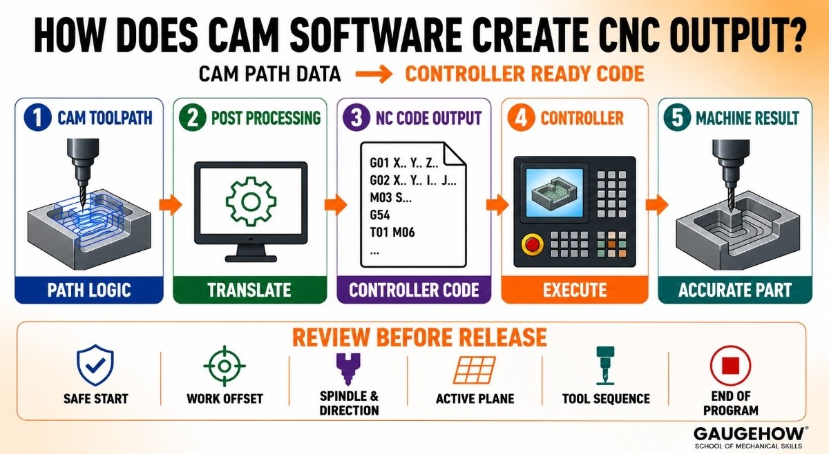
CAM software creates output by translating internal path data into controller-specific code.
Toolpath logic inside the CAM environment is still processing data, not yet machine language.
Post processing performs that translation, so motion, syntax, and machine functions are expressed in a structure that the target controller can execute.
Toolpath To NC Code
Internal path logic describes motion and sequence in software terms.
NC code expresses the same intent through controller-readable program blocks, so the machine can interpret movement, spindle calls, and auxiliary functions in a precise order.
That shift changes review responsibility. Path quality alone is not enough once code exists.
Output has to be checked as code because controller behavior follows syntax, state, and block order rather than the software screen.
What a Post-Processor Changes
A post-processor changes internal CAM logic into a machine-specific language structure.
Axis formatting, canned cycles, line syntax, coordinate output, and auxiliary calls are all shaped there, so one post can create confident output while another introduces avoidable release risk.
That is why post quality cannot be treated as a minor technical detail. Poor translation weakens the controller's trust.
Strong translation keeps execution logic aligned with the real machine, so the path seen in CAM remains close to the machine response seen at prove-out.
Why Output Changes By Controller
Controller differences change output because syntax, machine configuration, and available functions differ across platforms.
Fanuc, Siemens, Haas, turn-mill systems, and multi-axis machines all impose different translation demands, so identical geometry can still produce different controller code.
Machine architecture adds another layer. Axis naming, kinematic structure, and supported interpolation modes all affect output.
Once the controller and machine configuration are considered together, variation in code structure becomes expected instead of surprising.
What Needs Review Before Release
Release review should focus on execution logic rather than on visual comfort.
Safe start blocks, work offset calls, spindle direction, active plane, tool sequence, and end-of-program behavior all deserve attention because those elements control how the machine interprets state during execution.
A release that ignores those details may still pass surface-level inspection. A release that checks them directly is far more likely to survive prove-out with fewer surprises.
That is why the controller code needs its own review pass after the CAM work appears finished.
What Toolpaths And Output Control
CAM decisions change the part through four main channels. Cycle time changes through path efficiency and transition length.
Surface quality changes through finishing motion and cusp control. Tool life changes through load distribution and engagement behavior. Machine risk changes through translation quality and state clarity.
Earlier decisions shape every later result. Weak roughing paths extend cycle time and leave unstable stock for finishing. Poor finishing passes reduce surface consistency and blur final geometry.
Faulty post logic may generate code that appears clean yet behaves poorly at the controller. CAM quality should therefore be judged by machining effect, not interface polish.
What CAM Cannot Decide Alone
CAM cannot decide the smartest setup reference by itself. CAM cannot decide the best sequence for part stability by itself.
CAM cannot decide live controller state, revision confidence, or release readiness by itself. Those judgments sit beyond toolpath generation, so engineering review still owns the final outcome.
The setup reference judgment comes first because the datum choice shapes everything after it. Sequence judgment follows because the operation order controls stock condition, support, and access.
Work offset judgment then affects where the motion lands in real space. Controller state judgment decides how the code will actually begin or restart.
Revision judgment protects the job from stale geometry or stale tooling. Release judgment closes the loop by deciding whether all prior layers are aligned.
That section is where CAM becomes serious engineering rather than software operation. Once those judgments are kept visible, output is reviewed with more discipline and trusted with more reason.
How Does Safe Restart Logic Work?
Safe restart logic begins with one fact that broad software pages often miss. Block position alone is misleading.
A cursor can sit on a valid line while the controller state is incomplete, and an incomplete state changes how the next block will be interpreted.
Several elements have to be rebuilt together. Active mode must match the upcoming motion. Work offset must match the setup reference. Spindle state and coolant condition must support the next cut.
Tool identity must match the programmed sequence. Because each element affects execution logic, restart confidence comes from state recovery, not from line selection alone.
Work offset changes restart confidence sharply. A valid program block under one offset can become dangerous under another because physical location changes while text stays the same.
That is why restart review has to connect current position, active offset, next motion, and machine state into one picture instead of checking them separately.
Post output also stops helping at a certain point. A correct file cannot guarantee that a live controller still holds the right conditions for a mid-program resume.
Local edits are reasonable when state dependencies are short, the sequence is obvious, and geometry links are easy to trace.
Reposting is smarter when multiple assumptions have shifted, because state reconstruction becomes harder to trust and prove-out risk rises quickly.
How To Choose CAM Software
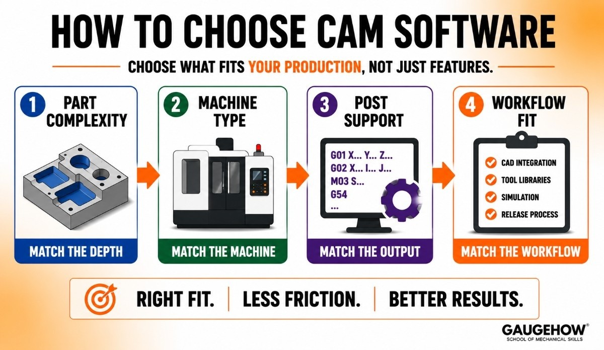
CAM software should be chosen against real production needs, not against broad feature claims.
Part complexity, machine type, post support, and workflow fit all shape whether a package will reduce friction or simply move it to another stage of the process.
Match Part Complexity
Part complexity should decide the required depth first. Prismatic 2.5D work, dense surfacing, simultaneous multi-axis motion, and mill-turn work all need different levels of toolpath sophistication.
A package that handles one category well may become restrictive once another category enters regular production.
Match Machine Type
Machine type should shape software evaluation early. Routers, VMCs, HMCs, lathes, turn-mill platforms, and 5-axis machines all place different demands on simulation, post-processing, and kinematic handling.
A good fit comes from matching software to machine behavior, not simply to interface preference.
Match Post Support
Post support is part of output confidence, not an add-on. Even good CAM logic loses value when translation is weak, because controller code is what the machine actually follows.
A package with dependable post support usually reduces release effort more than a package with broader surface features alone.
Match Workflow Fit
Workflow fit determines whether the software helps with daily work or adds drag. CAD integration, tool libraries, template strength, simulation depth, and release structure all belong here.
Once the package aligns with how programs are actually built, checked, revised, and released, productivity becomes much more durable.
CAM Software FAQs
What Is CAM Software In CNC?
CAM software is the process layer between design and machining. It turns geometry into setup logic, toolpaths, simulation data, and controller-ready output, so a CNC machine can execute an organized manufacturing plan.
How Does CAM Software Create Toolpaths?
CAM software creates toolpaths by combining model geometry, stock condition, tool data, and machining strategy into cutter motion. Because those variables are solved together, path behavior can be simulated, checked, and refined before release.
Does CAM Software Generate G-Code?
CAM software generates controller-ready code after internal path data passes through post-processing. Toolpath logic alone is not yet machine language, so post-translation is what converts machining intent into executable program blocks.
What Does a Post-Processor Do?
A post-processor translates CAM path data into controller-specific code. Syntax, axis output, canned cycles, and machine functions are all shaped there, so translation quality has a direct effect on release confidence and machine response.
Mechanical Engineering Courses That Industry Actually Uses
Learn Tools of Design & CAD, Analysis & Simulation, Automation & Robotics, and Industry 4.0 used in modern factories.
Join 40+ Mech Courses like GD&T, Siemens NX, SolidWorks, CATIA V5, AutoCAD, ANSYS (FEA & Fluent), ABAQUS, Creo, Fusion 360, CNC Programming, Digital Twins, Python for Mechanical, and Industry 4.0.
Our Courses
Complete Course Library
Access to 40+ courses covering various fields like Design, Simulation, Quality, Manufacturing, Robotics, and more.


